Subaru Tribeca (2014 year). Instruction — part 8
NOTE
. When you finish entering the eighth
digit, an electronic tone will sound for
30 seconds.
. If the interval between one push of
the switch and the next exceeds 5
seconds, an error will occur. In this
event, perform the procedure again
beginning with part 4. If an error occurs
six times, perform the procedure again
starting with part 3.
8. Before the electronic tone stops
sounding, use the power door locking
switch to reenter the transmitter code
beginning with the leftmost digit.
NOTE
If you do not start entering the number
using the lock knob before the electro-
nic tone stops sounding, an error will
occur. In this event, perform the proce-
dure again beginning with part 3.
9. When you have finished entering the
code a second time, an electronic tone will
sound for 1 second and automatic door
locking and unlocking operation will take
place once to indicate completion of
registration, provided the code entered
the second time is identical to that entered
the first time.
NOTE
If the code entered the second time is
not identical to the code entered the
first time, an error will occur. In this
event, perform the procedure again
beginning with part 5. If an error occurs
five times, perform the procedure again
starting with part 3.
10. If you wish to program another trans-
mitter code into the system (up to four
transmitter codes can be programmed into
the system), perform the procedure begin-
ning with part 4. When you have finished
programming all of the necessary trans-
mitter codes into the system, remove the
key from the ignition switch.
11. Test every registered transmitter to
confirm correct operation.
! Deleting old transmitter codes
The control unit of the remote keyless
entry system has four memory locations to
store transmitter codes, giving it the ability
to operate with up to four transmitters.
When you lose a transmitter, the lost
transmitter’s code remains in the memory.
For security reasons, lost transmitter
codes should be deleted from the mem-
ory.
To delete old transmitter codes, program
four transmitter codes into the system. If
you have only one current transmitter,
program it four times. If you have two
current transmitters, program each one
twice. If you have three current transmit-
ters, program two of them once and the
third one twice. This process will leave
only current transmitter codes in the
system’s memory.
NOTE
Make sure no one else is operating
their keyless entry system within range
of your vehicle when programming
transmitters. If someone else were to
operate their remote transmitter while
you are programming your transmit-
ters, it is possible that their transmitter
code will be programmed into your
system, allowing them unauthorized
access to your vehicle.
Keys and doors
2-15
2-16
Keys and doors
Alarm system
The alarm system helps to protect your
vehicle and valuables from theft. The horn
sounds and the turn signal lights flash if
someone attempts to break into your
vehicle.
The system can be armed and disarmed
with the remote transmitter.
The system does not operate when the
key is inserted into the ignition switch.
Your vehicle’s alarm system has been set
for activation at the time of shipment from
the factory. You can set the system for
deactivation yourself or have it done by
your SUBARU dealer.
& System operation
The alarm system will give the following
alarms when triggered.
. The vehicle’s horn will sound for 30
seconds.
. The turn signal lights will flash for 30
seconds.
If any of the doors or the rear gate remains
open after the 30-second period, the horn
will continue to sound for a maximum of 3
minutes. If any of the doors or the rear
gate is closed while the horn is sounding,
the horn will stop sounding with a delay of
up to 30 seconds.
The alarm is triggered by:
. Opening any of the doors or the rear
gate
. Physical impact to the vehicle, such as
forced entry (only vehicles with shock
sensors (dealer option))
NOTE
The alarm system can be set to trigger
the illumination of the following interior
lights.
. Dome light (illuminates only when
the dome light switch is in the “DOOR”
position)
. Map lights
The notifications regarding the dome
light and the map lights are deactivated
as the factory setting. A SUBARU
dealer can activate the system. Contact
your SUBARU dealer for details.
& Activating and deactivating
the alarm system
To change the setting of your vehicle’s
alarm system for activation or deactiva-
tion, do the following.
1. Disarm the alarm system. Refer to
“Disarming the system” F2-18.
2. Sit in the driver’s seat and shut all
doors and the rear gate.
3. Turn the ignition switch to the “ON”
position.
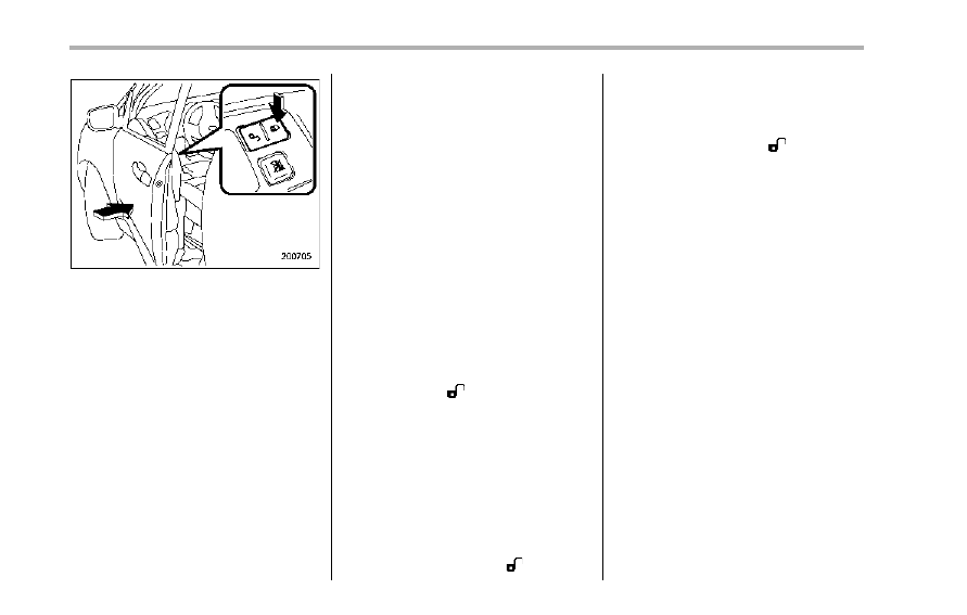
4. Hold down the UNLOCK side of the
driver’s power door locking switch, open
the driver’s door within the following 1
second, and wait 10 seconds without
releasing the switch. The setting will then
be changed as follows.
If the system was previously activated:
The odometer/trip meter screen displays
“AL oF” and the horn sounds twice,
indicating that the system is now deacti-
vated.
If the system was previously deacti-
vated:
The odometer/trip meter screen displays
“AL on” and the horn sounds once,
indicating that the system is now acti-
vated.
NOTE
You may have the above setting
change done by your SUBARU dealer.
& If you have accidentally trig-
gered the alarm system
! To stop the alarm
Do any of the following operations.
. Press any button on the remote trans-
mitter.
. Turn the ignition switch to the “ON”
position.
& Arming the system
! To arm the system using remote
transmitter
1. Close all windows and the moonroof.
2. Remove the key from the ignition
switch.
3. Open the doors and get out of the
vehicle.
4. Make sure that the engine hood is
locked.
5. Close all doors and the rear gate.
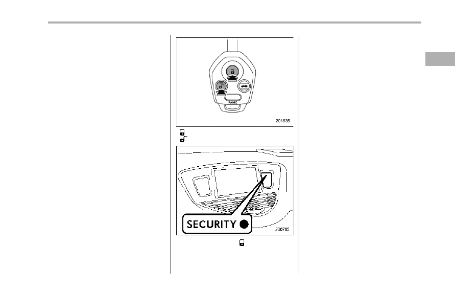
: Press to Arm the system.
: Press to Disarm the system.
6. Briefly press the “ ” button (for less
than 2 seconds). All doors and the rear
gate will lock, an electronic chirp will
sound once, the turn signal lights will flash
once and the indicator lights will start
flashing rapidly. After rapid flashing for 30
seconds (standby time), the indicator
lights will then flash slowly (twice approxi-
mately every 2 seconds), indicating that
the system has been armed for surveil-
lance.
If any of the doors or the rear gate is not
fully closed, an electronic chirp sounds
five times, the turn signal lights flash five
times to alert you that the doors or the rear
gate are not properly closed. When you
close the door, the system will automati-
cally arm and doors will automatically lock.
! To arm the system using power
door locking switches
1. Close all windows.
2. Remove the key from the ignition
switch.
3. Open the doors and get out of the
vehicle.
4. Make sure that the engine hood is
locked.
5. Close the doors and the rear gate but
leave only the driver’s door or the front
passenger’s door open.
Keys and doors
2-17
– CONTINUED –
2-18
Keys and doors
6. Push the front side (“LOCK” side) of
the power door locking switch to set the
door locks.
7. Close the door. An electronic chirp will
sound once, the turn signal lights will flash
once and the indicator lights will start
flashing rapidly. After rapid flashing for 30
seconds (standby time), the indicator
lights will then flash slowly (twice approxi-
mately every 2 seconds), indicating that
the system has been armed for surveil-
lance.
NOTE
. The system can be armed even if the
engine hood, the windows and/or
moonroof are opened. Always make
sure that they are fully closed before
arming the system.
. The 30-second standby time can be
eliminated if you prefer. Have it per-
formed by your SUBARU dealer.
. The system is in the standby mode
for a 30-second period after locking the
doors with the remote transmitter. The
security indicator light will flash at
short intervals during this period.
. If any of the following actions is
done during the standby period, the
system will not switch to the surveil-
lance state.
– Doors are unlocked using the
remote transmitter.
– Any of the doors or the rear gate
is opened.
– Ignition switch is turned to the
“ON” position.
& Disarming the system
Briefly press the “ ” button (for less than
2 seconds) on the remote transmitter. The
driver’s door will unlock, an electronic
chirp will sound twice and the turn signal
lights will flash twice. The flashing of the
security indicator light will then change
slowly (once approximately every 3 sec-
onds from twice approximately every 2
seconds), indicating that the alarm system
has been disarmed.
To unlock all other doors and the rear
gate, briefly press the “ ” button a
second time within 5 seconds.
NOTE
If the interval between the first and
second presses of the “ ” button (for
unlocking of all of the doors and the
rear gate) is extremely short, the sys-
tem may not respond.
! Emergency disarming
If you cannot disarm the system using the
transmitter (i.e. the transmitter is lost,
broken or the transmitter battery is too
weak), you can disarm the system without
using the transmitter.
The system can be disarmed if you turn
the ignition switch from the “LOCK” to the
“ON” position with a registered key.
& Valet mode
When you choose the valet mode, the
alarm system does not operate. In valet
mode, the remote transmitter is used only
for locking and unlocking the doors and
rear gate and panic activation.
To enter the valet mode, change the
setting of your vehicle’s alarm system for
deactivation mode. Refer to “Activating
and deactivating the alarm system” F2-
16. The security indicator light will con-
tinue to flash once every 3 seconds
indicating that the system is in the valet
mode.
To exit valet mode, change the setting of
your vehicle’s alarm system for activation
mode. Refer to “Activating and deactivat-
ing the alarm system” F2-16.
& Passive arming
When passive arming mode has been
programmed by the dealer, arming of the
system is automatically accomplished
without using the remote transmitter. Note
that in this mode, DOORS MUST BE
MANUALLY LOCKED.
! To enter the passive mode
If you wish to program the passive arming
mode, have it done by your SUBARU
dealer.
! Arming the system
CAUTION
In passive mode, the system will
automatically activate the alarm but
WILL NOT automatically lock the
doors. In order to lock the doors
you must either lock them as in-
dicated in step 4 below or with the
key once they have been closed.
Failure to lock the doors instructionly
will result in a higher security risk.
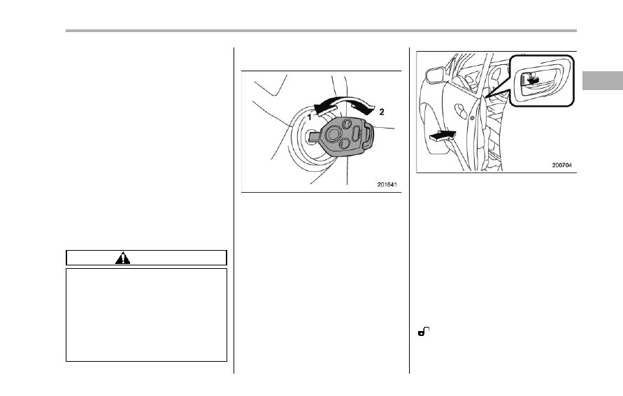
1. Turn the ignition switch to the “ON”
position.
1)
LOCK
2)
ON
2. Turn the ignition switch from “ON” to
“LOCK” position and remove the key from
the ignition switch.
3. Open the doors and get out of the
vehicle.
4. Before closing the doors, lock all doors
with the inside door lock levers.
5. Close the doors. The system will
automatically arm after 1 minute.
In the passive mode, the system can also
be armed with the remote transmitter or
with the power door locking switches. If
the remote transmitter or power door
locking switch is used to lock the vehicle,
arming will take place immediately regard-
less of whether or not the passive mode
has been selected.
! Disarming the system
To disarm the system, briefly press the
“
” button on the transmitter.
Keys and doors
2-19
– CONTINUED –
2-20
Keys and doors
& Tripped sensor identification
The security indicator light flashes when
the alarm system has been triggered.
Also, the number of flashes indicates the
location of unauthorized intrusion or the
severity of impact on the vehicle.
When the ignition switch is turned to the
“ON” position, the indicator light will
illuminate for 1 second and then flash as
follows.
. When a door or rear gate was opened:
5 times
. When the ignition switch was turned to
the “ON” position by using a key not
registered with your immobilizer system: 3
times
. When a strong impact or multiple
impacts were sensed: twice (only vehicles
with shock sensors (dealer option))
. When a light impact was sensed: once
(only vehicles with shock sensors (dealer
option))
NOTE
Any of the above indicator light flash-
ing patterns will recur each time the
ignition switch is turned to the “ON”
position. Rearming the alarm system
cancels the flashing pattern of the
security indicator light.
& Shock sensors (dealer op-
tion)
The shock sensors trigger the alarm
system when they sense impacts applied
to the vehicle and when any of their
electric wires is cut. The alarm system
causes the horn to sound and the turn
signal lights to flash for a short time when
the sensed impact is weak, but it warns of
a strong impact or multiple impacts by
sounding the horn and flashing the turn
signal lights, both lasting approximately 30
seconds.
If you desire, your SUBARU dealer can
connect them and set them for activation
or deactivation.
NOTE
. The shock sensors are not always
able to sense impacts caused by break-
ing in, and cannot sense an impact that
does not cause vibration (such as
breaking the glass using a rescue
hammer).
. The shock sensors may sense vi-
bration like those shown in the follow-
ing list and trigger the alarm system.
Select the settings of the alarm system
and shock sensors appropriately de-
pending on where you usually park
your vehicle.
Example:
– Vibration from construction site
– Vibration in multistory car park
– Vibration from trains
. You can have the sensitivity of the
shock sensors adjusted to your pre-
ference by your SUBARU dealer.
Child safety locks
WARNING
Always use the child safety lock
whenever a child rides in the rear.
Serious injury could result if a child
accidentally opened the door and
fell out.
Each rear door has a child safety lock that
prevents the door from being opened even
if the inside door handle is pulled.
When the child safety lock lever is in the
lock position, the door cannot be opened
from inside regardless of the position of
the inner door handle lock lever. The door
can only be opened from the outside.
Windows
& Power windows
WARNING
To avoid serious personal injury
caused by entrapment, always con-
form to the following instructions
without exception.
. When operating the power win-
dows, be extremely careful to
prevent anyone’s fingers, arms,
neck or head from being caught
in the window.
. Always lock the passengers’ win-
dows using the lock switch when
children are riding in the vehicle.
. Before leaving the vehicle, al-
ways remove the key from the
ignition switch for safety and
never allow an unattended child
to remain in the vehicle. Failure
to follow this procedure could
result in injury to a child operat-
ing the power window.
The power windows operate only when
the ignition switch is in the “ON” position.
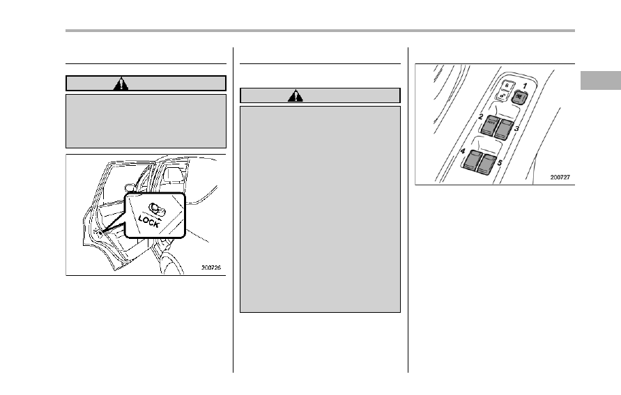
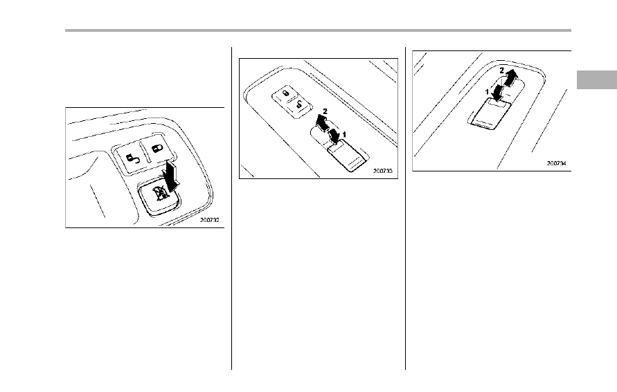
! Driver’s side switches
1)
Lock switch
2)
For driver’s window
3)
For front passenger’s window
4)
For rear left window
5)
For rear right window
All door windows can be controlled by the
power window switch cluster at the driver
side door.
Keys and doors
2-21
– CONTINUED –

2-22
Keys and doors
! Operating the driver’s window
1)
Open
2)
Automatically open
To open:
Push the switch down lightly and hold it.
The window will open as long as the
switch is held.
This switch also has a one-touch auto
down feature that allows the window to be
opened fully without holding the switch.
Push the switch down until it clicks and
release it, and the window will fully open.
To stop the window halfway, pull the
switch up lightly.
To close:
Pull the switch up lightly and hold it. The
window will close as long as the switch is
held.
! Operating the passengers’ win-
dows
To open:
Push the appropriate switch down and
hold it until the window reaches the
desired position.
To close:
Pull the switch up and hold it until the
window reaches the desired position.
! Locking the passengers’ win-
dows
Push the lock switch. When the lock
switch is in the “LOCK” position, the
passengers’ windows cannot be opened
or closed.
Press the switch again to cancel the
passengers’ window locking.
NOTE
When the lock switch is pushed to the
“LOCK” position, the indicator lights in
the passenger’s window switches (in-
cluded in the power window switch
cluster on the driver’s door) all turn off.
! Passengers’ side switches
Front passenger’s window switch
1)
Open
2)
Close
Rear passengers’ window switches
1)
Open
2)
Close
To open:
Push the switch down and hold it until the
window reaches the desired position.
To close:
Pull the switch up and hold it until the
window reaches the desired position.
When the lock switch on the power
window switch cluster, located on the
driver’s side door, is in the “LOCK”
position, the passengers’ windows cannot
be operated with the passengers’
switches.
Keys and doors
2-23
2-24
Keys and doors
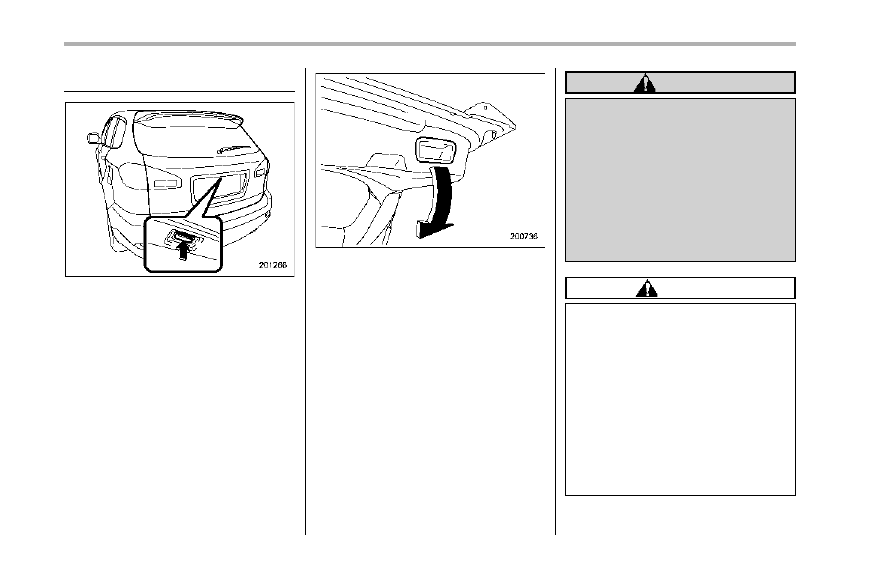
Rear gate
The rear gate can be locked and unlocked
using any of the following systems.
. Power door locking switch: Refer to
“Power door locking switches” F2-7.
. Remote keyless entry system (if
equipped): Refer to “Remote keyless entry
system” F2-8.
To open:
First unlock the rear gate lock then push
the button.
To close:
Lower the rear gate slowly and push down
firmly until the latch engages.
The rear gate can be lowered easily if you
pull it down holding the recessed grip.
WARNING
. To prevent dangerous exhaust
gas from entering the vehicle,
always keep the rear gate closed
while driving.
. Do not attempt to shut the rear
gate while holding the recessed
grip. Also avoid closing the rear
gate by pulling on the recessed
grip from inside the cargo space.
There is a danger of your hand
being caught and injured.
CAUTION
. Do not jam a plastic bag in or
place cellophane tape on the rear
gate stays or scratch the stays
while loading or unloading cargo.
That could cause leakage of gas
from the stays, which may result
in their inability to hold the rear
gate open.
. Be careful not to hit your head or
face on the rear gate when open-
ing or closing the rear gate and
when loading or unloading car-
go.
NOTE
If the rear gate cannot be unlocked due
to a discharged vehicle battery, a
malfunction in the door locking/unlock-
ing system or other causes, you can
unlock it by instructionly operating the
rear gate lock release lever. For the
procedure, refer to “Rear gate – if the
rear gate cannot be unlocked” F9-18.
Moonroof (if equipped)
WARNING
Never let anyone’s hands, arms,
head or any objects protrude from
the moonroof. A person could be
seriously injured if the vehicle stops
suddenly or turns sharply or if the
vehicle is involved in an accident.
To avoid serious personal injury
caused by entrapment, always con-
form to the following instructions
without exception.
. Before closing the moonroof,
make sure that no one’s hands,
arms, head or other objects will
be accidentally caught in the
moonroof.
. Before leaving the vehicle, al-
ways remove the key from the
ignition switch for safety and
never allow an unattended child
to remain in the vehicle. Failure
to follow this procedure could
result in injury to a child operat-
ing the moonroof.
. Never try to check the anti-en-
trapment function by deliberately
placing part of your body in the
moonroof.
CAUTION
. Do not sit on the edge of the open
moonroof.
. Do not operate the moonroof if
falling snow or extremely cold
conditions have caused it to
freeze shut.
. The anti-entrapment function
does not operate when the moon-
roof is being tilted down. Be sure
to confirm that it is safe to do so
before tilting the moonroof down.
The moonroof has both tilting and sliding
functions.
The moonroof operates only when the
ignition switch is in the “ON” position.
Keys and doors
2-25
– CONTINUED –
2-26
Keys and doors
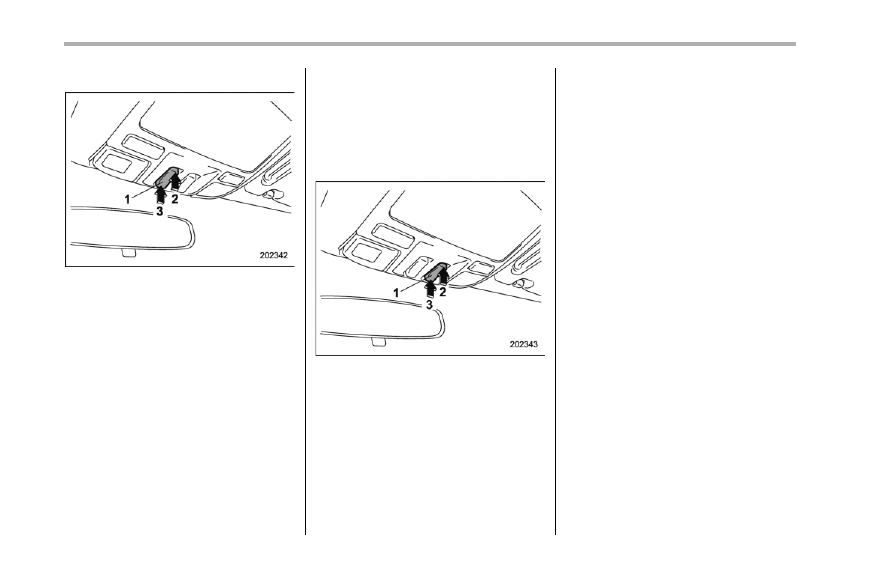
& Tilt function
1)
Tilt switch
2)
Raise
3)
Lower
The tilting function will only operate when
the moonroof is fully closed.
Push the rear side of the “Tilt” switch to
raise the moonroof.
Push the front side of the “Tilt” switch to
lower the moonroof.
Release the switch after the moonroof has
been raised or has been lowered com-
pletely. Pushing the switch continuously
may cause damage to the moonroof.
NOTE
One-touch operation does not take
place when the moonroof is raised or
lowered. Push the switch continuously
to raise or lower the moonroof.
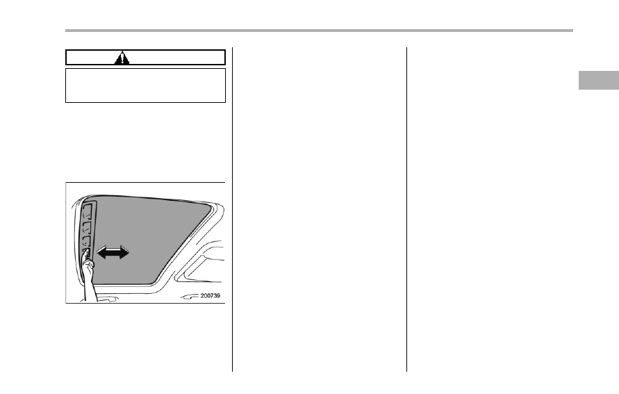
& Sliding function
1)
Open/Close switch
2)
Open
3)
Close
Push the “Open/Close” switch rearward to
open the moonroof. The sun shade will
also be opened together with the moon-
roof.
Push the “Open/Close” switch forward to
close the moonroof. The moonroof will
stop halfway. Push it again to close the
moonroof completely.
To stop the moonroof at a selected mid-
way position while opening or closing it,
momentarily push the switch to the
“OPEN” or “CLOSE” side.
After washing the vehicle or after it rains,
wipe away water on the roof prior to
opening the moonroof to prevent drops
of water from falling into the passenger
compartment.
& Anti-entrapment function
When the moonroof senses a substantial
enough object trapped between its glass
and the vehicle’s roof during closure, it
automatically moves back to either of the
following positions according to the point
at which it senses the object.
. When the moonroof senses the object
at a point between the halfway stop
position and fully closed position, it moves
back to the halfway stop position and
stops there.
. When the moonroof senses the object
at a point between the halfway stop
position and fully open position, it moves
back to the fully open position and stops
there.
The anti-entrapment function may also be
activated by a strong shock on the moon-
roof even when there is nothing trapped.
CAUTION
Never attempt to test this function
using fingers, hands or other parts
of your body.
NOTE
For the sake of safety, it is recom-
mended that you avoid driving with the
moonroof fully opened.
& Sun shade
The sun shade can be slid forward or
backward by hand while the moonroof is
closed.
If the moonroof is opened, the sun shade
also moves back.
Keys and doors
2-27
— — — — — — — — — — — — — — — — — — — — — — — — — — — — — — — — — — — — — — — —
— — — — — — — — — — — — — — — — — — — — — — — — — — — — — — — — — — — — — — — —
— — — — — — — — — — — — — — — — — — — — — — — — — — — — — — — — — — — — — — — —
— — — — — — — — — — — — — — — — — — — — — — — — — — — — — — — — — — — — — — — —
— — — — — — — — — — — — — — — — — — — — — — — — — — — — — — — — — — — — — — — —
— — — — — — — — — — — — — — — — — — — — — — — — — — — — — — — — — — — — — — — —
— — — — — — — — — — — — — — — — — — — — — — — — — — — — — — — — — — — — — — — —
— — — — — — — — — — — — — — — — — — — — — — — — — — — — — — — — — — — — — — — —
— — — — — — — — — — — — — — — — — — — — — — — — — — — — — — — — — — — — — — — —
— — — — — — — — — — — — — — — — — — — — — — — — — — — — — — — — — — — — — — — —
— — — — — — — — — — — — — — — — — — — — — — — — — — — — — — — — — — — — — — — —
— — — — — — — — — — — — — — — — — — — — — — — — — — — — — — — — — — — — — — — —
— — — — — — — — — — — — — — — — — — — — — — — — — — — — — — — — — — — — — — — —
Ignition switch . . . . . . . . . . . . . .
3-3
LOCK. . . . . . . . . . . . . . . . ..
3-3
Acc. . . . . . . . . . . . . . . . . .
3-4
ON. . . . . . . . . . . . . . . . . ..
3-4
START . . . . . . . . . . . . . . . .
3-4
Key reminder chime . . . . . . . . . . .
3-4
Ignition switch light . . . . . . . . . . . .
3-4
Hazard warning flasher. . . . . . . . . ...
3-5
Meters and gauges. . . . . . . . . . . ..
3-5
Combination meter illumination . . . . . . ...
3-5
Canceling the function for meter needle/gauge
movement and combination meter sequential
illumination upon turning on the ignition
switch. . . . . . . . . . . . . . . ...
3-5
Speedometer. . . . . . . . . . . . . ...
3-6
Odometer. . . . . . . . . . . . . . .
3-6
Double trip meter . . . . . . . . . . . .
3-7
Tachometer . . . . . . . . . . . . . . .
3-7
Fuel gauge. . . . . . . . . . . . . . ..
3-8
Temperature gauge . . . . . . . . . . . .
3-8
Warning and indicator lights . . . . . . . ..
3-9
Seatbelt warning light and chime . . . . . . 3-10
SRS airbag system warning light . . . . . .
3-11
Front passenger’s frontal airbag ON and OFF
indicators. . . . . . . . . . . . . . . 3-12
CHECK ENGINE warning light/Malfunction
indicator light. . . . . . . . . . . . ... 3-12
Charge warning light . . . . . . . . . . .. 3-13
Oil pressure warning light . . . . . . . . .. 3-13
AT OIL TEMP warning light . . . . . . . . . 3-13
Rear differential oil temperature warning
light . . . . . . . . . . . . . . . .
3-13
Low tire pressure warning light . . . . . . ..
3-14
ABS warning light. . . . . . . . . . . ..
3-15
Brake system warning light. . . . . . . .
3-16
Low fuel warning light . . . . . . . . . ...
3-17
Door open warning light . . . . . . . . .
3-17
Windshield washer fluid warning light . . . .
3-17
All-Wheel Drive warning light . . . . . . . .
3-18
Vehicle Dynamics Control warning light (U.S.-
spec models and Canada-spec. models)/Vehicle
Dynamics Control operation indicator light (all
models) . . . . . . . . . . . . . . ...
3-18
Traction Control system OFF indicator light
(U.S.-spec models and Canada-spec.
models) . . . . . . . . . . . . . . ...
3-19
Vehicle Dynamics Control warning light (Latin
America-spec. models)/Traction Control OFF
indicator light (Latin America-spec. models) . .
3-19
Security indicator light. . . . . . . . . ...
3-21
SPORT mode indicator light . . . . . . . ...
3-21
Select lever/Gear position indicator . . . . .
3-21
Turn signal indicator lights. . . . . . . . .
3-21
High beam indicator light . . . . . . . . ...
3-22
Cruise control indicator light. . . . . . . ..
3-22
Cruise control set indicator light . . . . . .
3-22
Headlight indicator light . . . . . . . . . .
3-22
Front fog light indicator light. . . . . . . ..
3-22
Clock . . . . . . . . . . . . . . . . ..
3-22
Outside temperature indicator . . . . . . ..
3-23
Low outside temperature warning . . . . . ..
3-24
Instruments and controls
3
Instruments and controls
Multi function display (vehicles without a
genuine SUBARU navigation system) . . ... 3-24
Current fuel consumption . . . . . . . . ... 3-25
Average fuel consumption . . . . . . . . .. 3-25
Driving range on remaining fuel. . . . . . .. 3-26
Journey time. . . . . . . . . . . . . .. 3-27
Light control switch . . . . . . . . . . ... 3-27
Headlights. . . . . . . . . . . . . . .. 3-28
High/low beam change (dimmer). . . . . . . 3-28
Headlight flasher . . . . . . . . . . . . 3-28
Daytime running light system . . . . . . . . 3-29
Turn signal lever . . . . . . . . . . . . 3-29
Illumination brightness control . . . . . . . 3-29
Headlight beam leveler (if equipped) . . . . 3-30
Parking light switch. . . . . . . . . . ...
3-32
Front fog light switch . . . . . . . . . .
3-32
Wiper and washer. . . . . . . . . . . ..
3-33
Windshield wiper and washer switches . . . ..
3-34
Rear window wiper and washer switch . . . ...
3-35
Windshield wiper deicer. . . . . . . . .
3-36
Rear window defogger button . . . . . . ..
3-37
Mirrors . . . . . . . . . . . . . . . .
3-38
Type A inside mirror (if equipped) . . . . . ..
3-38
Type B inside mirror (if equipped) . . . . . ..
3-38
Type C inside mirror (if equipped) . . . . . ..
3-41
Outside mirrors . . . . . . . . . . . . .
3-42
Tilt steering wheel . . . . . . . . . . . .
3-44
Horn. . . . . . . . . . . . . . . . .
3-44
Нет комментариевНе стесняйтесь поделиться с нами вашим ценным мнением.
Текст