Subaru Tribeca (2014 year). Instruction — part 23
WARNING
. When replacing a tire, you must
use a tire that is of the same size,
circumference, speed symbol
and load index as the original
tires listed on the tire placard.
Using tires of other sizes, cir-
cumferences or constructions
may result in severe mechanical
damage to the drive train of your
vehicle and may affect ride,
handling, braking, speedometer/
odometer calibration, and clear-
ance between the body and tires.
It also may be dangerous and
lead to loss of vehicle control.
. You must install four tires that are
of the same size, circumference,
construction, manufacturer,
brand (tread pattern), degree of
wear, speed symbol and load
index. Mixing tires of different
types, sizes or degrees of wear
can result in damage to the
vehicle’s power train. Use of
different types or sizes of tires
can also dangerously reduce
controllability and braking per-
formance and can lead to an
accident.
. Use only radial tires. Do not use
radial tires together with belted
bias tires and/or bias-ply tires.
Doing so can dangerously re-
duce controllability, resulting in
an accident.
& Wheel replacement
When replacing wheels due, for example,
to damage, make sure the replacement
wheels match the specifications of the
wheels that are fitted as standard equip-
ment. Replacement wheels are available
from SUBARU dealers.
WARNING
Use only those wheels that are
specified for your vehicle. Wheels
not meeting specifications could
interfere with brake caliper opera-
tion and may cause the tires to rub
against the wheel well housing dur-
ing turns. The resulting loss of
vehicle control could lead to an
accident.
Aluminum wheels
. Aluminum wheels can be scratched
and damaged easily. Handle them care-
fully to maintain their appearance, perfor-
mance, and safety.
. When any of the wheels are removed
and replaced for tire rotation or to change
a flat tire, always check the tightness of
the wheel nuts after driving approximately
600 miles (1,000 km). If any nut is loose,
tighten it to the specified torque.
– For the wheel nut tightening torque,
refer to “Tires” F12-8.
– For the wheel nut tightening proce-
dure, refer to “Changing a flat tire” F9-
6.
. Never apply oil to the threaded parts,
wheel nuts, or tapered surface of the
wheel.
. Never let the wheel rub against sharp
protrusions or curbs.
. When wheel nuts, balance weights, or
the center cap is replaced, be sure to
replace them with genuine SUBARU parts
designed for the specific wheel.
Maintenance and service
11-27
11-28
Maintenance and service
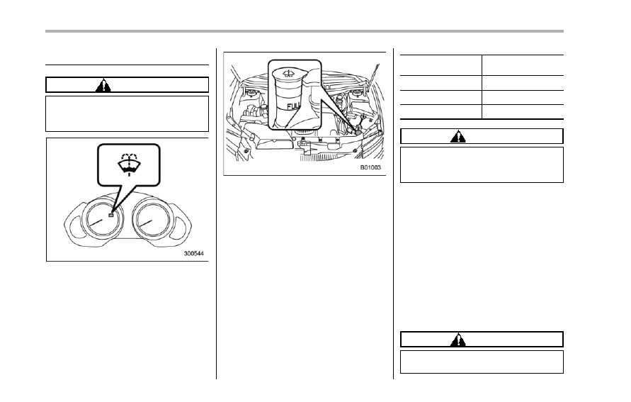
Windshield washer fluid
CAUTION
Never use engine coolant as washer
fluid because it could cause paint
damage.
If you spray washer fluid on the windshield
but the windshield washer fluid warning
light illuminates or the supply of washer
fluid appears to diminish, add washer fluid
in the tank.
Remove the washer tank filler cap, then
add washer fluid until it reaches the
“FULL” mark on the tank.
After adding washer fluid, make sure the
windshield washer fluid warning light has
turned off.
Use windshield washer fluid. If windshield
washer fluid is unavailable use clean
water.
In areas where water freezes in winter,
use an anti-freeze type windshield washer
fluid. SUBARU Windshield Washer Fluid
contains 58.5% methyl alcohol and 41.5%
surfactant, by volume. Its freezing tem-
perature varies according to how much it
is diluted, as indicated in the following
table.
Washer Fluid
Concentration
Freezing
Temperature
30%
10.48F (−128C)
50%
−48F (−208C)
100%
−498F (−458C)
CAUTION
Never use engine coolant as washer
fluid because it could cause paint
damage.
In order to prevent freezing of washer
fluid, check the freezing temperatures in
the table above when adjusting the fluid
concentration to the outside temperature.
If you fill the reservoir tank with a fluid with
a different concentration from the one
used previously, purge the old fluid from
the piping between the reservoir tank and
washer nozzles by operating the washer
for a certain period of time. Otherwise, if
the concentration of the fluid remaining in
the piping is too low for the outside
temperature, it may freeze and block the
nozzles.
CAUTION
. Adjust the washer fluid concen-
tration appropriately for the out-
side temperature. If the concen-
tration is inappropriate, sprayed
washer fluid may freeze on the
windshield and obstruct your
view, and the fluid may freeze in
the reservoir tank.
. State or local regulations on
volatile organic compounds may
restrict the use of methanol, a
common windshield washer anti-
freeze additive. Washer fluids
containing non-methanol anti-
freeze agents should be used
only if they provide cold weather
protection without damaging
your vehicle’s paint, wiper blades
or washer system.
Replacement of wiper blades
Grease, wax, insects, or other materials
on the windshield or the wiper blade
results in jerky wiper operation and streak-
ing on the glass. If you cannot remove the
streaks after operating the windshield
washer or if the wiper operation is jerky,
clean the outer surface of the windshield
(or rear window) and the wiper blades
using a sponge or soft cloth with a neutral
detergent or mild abrasive cleaner. After
cleaning, rinse the windshield and wiper
blades with clean water. The windshield is
clean if beads do not form when you rinse
the windshield with water.
CAUTION
. Do not clean the wiper blades
with gasoline or a solvent, such
as paint thinner or benzine. This
will cause deterioration of the
wiper blades.
. When you wish to raise the
passenger-side wiper arm, first
raise the driver-side wiper arm.
Otherwise, the passenger-side
wiper assembly and driver-side
wiper assembly will touch each
other, possibly resulting in
scratches.
. While removing the wiper blades
from the wiper arms, do not
return the wiper arms to the
original positions. Otherwise,
the windshield surface may be
scratched.
. When returning the raised wiper
arms to the original positions,
carefully return the wiper arms
on the windshield while support-
ing them with your hands. You
should not return the wiper arms
to the windshield only by the
return spring. Otherwise, the wi-
per arms may be deformed and/
or the windshield surface may be
scratched.
. Return the passenger-side wiper
arm to its original position before
returning the driver-side wiper
arm to its original position.
Otherwise, the passenger-side
wiper assembly and driver-side
wiper assembly will touch each
other, possibly resulting in
scratches.
If you cannot eliminate the streaking even
after following this method, replace the
wiper blades using the following proce-
dures. Be sure to use genuine SUBARU
wiper blade rubbers as replacements.
Maintenance and service
11-29
– CONTINUED –
11-30
Maintenance and service
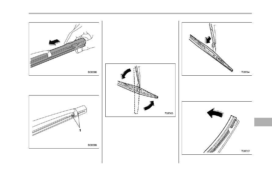
& Windshield wiper blade as-
sembly
1. Raise the windshield wiper arm on the
driver’s side.
2. Next, raise the windshield wiper arm
on the passenger’s side.
1)
Stopper
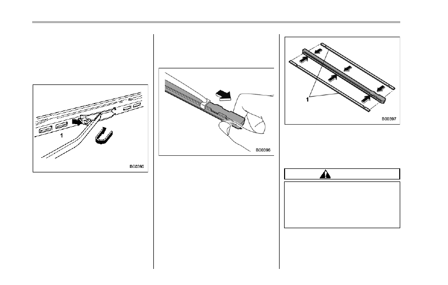
3. Remove the wiper blade assembly by
holding its pivot area and pushing it in the
direction shown by the arrow while de-
pressing the wiper blade stopper.
4. Install the wiper blade assembly to the
wiper arm. Make sure that it locks in place.
5. Lower the windshield wiper arm on the
passenger’s side slowly while supporting
it with your hands.
6. Next, lower the windshield wiper arm
on the driver’s side slowly while support-
ing it with your hands.
& Windshield wiper blade rub-
ber
1)
Metal support
1. Grasp the locked end of the blade
rubber assembly and pull it firmly until the
stoppers on the rubber are free of the
metal support.
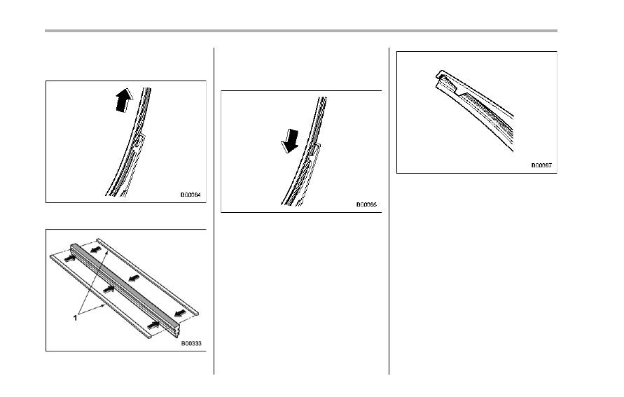
1)
Metal spines
2. If the new blade rubber is not provided
with two metal spines, remove the metal
spines from the old blade rubber and
install them in the new blade rubber.
CAUTION
Be sure to install each metal spine
so as to fit its groove completely on
the center ridge of the blade rubber.
Doing otherwise may result in dis-
location and breakage of the spine
during wiper operation.
3. Align the claws of the metal support
with the grooves in the rubber and slide
the blade rubber assembly into the metal
support until it locks.
1)
Stopper
4. Be sure to position the claws at the
end of the metal support between the
stoppers on the rubber as shown. If the
rubber is not retained properly, the wiper
blade may scratch the windshield.
& Rear window wiper blade
assembly
1. Raise the wiper arm off the rear
window.
2. Turn the wiper blade assembly coun-
terclockwise.
3. Pull the wiper blade assembly toward
you to remove it from the wiper arm.
& Rear window wiper blade
rubber
Maintenance and service
11-31
– CONTINUED –
11-32
Maintenance and service
1. Pull out the end of the blade rubber
assembly to unlock it from the plastic
support.
2. Pull the blade rubber assembly out of
the plastic support.
1)
Metal spines
3. If the new blade rubber is not provided
with two metal spines, remove the metal
spines from the old blade rubber and
install them in the new blade rubber.
4. Align the claws of the plastic support
with the grooves in the blade rubber
assembly, then slide the blade rubber
assembly into place.
Securely retain both ends of the rubber
with the stoppers on the plastic support
ends. If the rubber is not retained properly,
the wiper may scratch the rear window
glass.
5. Install the wiper blade assembly to the
wiper arm. Make sure that it locks in place.
6. Hold the wiper arm by hand and slowly
lower it in position.
Battery
WARNING
. Before beginning work on or near
any battery, be sure to extinguish
all cigarettes, matches, and light-
ers. Never expose a battery to an
open flame or electric sparks.
Batteries give off a gas which is
highly flammable and explosive.
. For safety, in case an explosion
does occur, wear eye protection
or shield your eyes when work-
ing near any battery. Never lean
over a battery.
. Do not let battery fluid contact
eyes, skin, fabrics, or paint be-
cause battery fluid is a corrosive
acid. If battery fluid gets on your
skin or in your eyes, immediately
flush the area with water thor-
oughly. Seek medical help imme-
diately if acid has entered the
eyes.
If battery fluid is accidentally
swallowed, immediately drink a
large amount of milk or water,
and seek medical attention im-
mediately.
. To lessen the risk of sparks,
remove rings, metal watchbands,
and other metal jewelry. Never
allow metal tools to contact the
positive battery terminal and any-
thing connected to it WHILE you
are at the same time in contact
with any other metallic portion of
the vehicle because a short cir-
cuit will result.
. Keep everyone including children
away from the battery.
. Charge the battery in a well-
ventilated area.
. Battery posts, terminals, and re-
lated accessories contain lead
and lead compounds, chemicals
known to the State of California
to cause cancer and reproductive
harm. Batteries also contain
other chemicals known to the
State of California to cause can-
cer. Wash hands after handling.
CAUTION
Never use more than 10 amperes
when charging the battery because
it will shorten battery life.
It is unnecessary to periodically check the
battery fluid level or periodically refill with
distilled water.
Maintenance and service
11-33
11-34
Maintenance and service
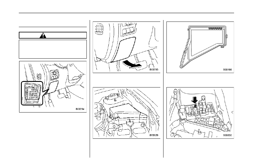
Fuses
CAUTION
Never replace a fuse with one hav-
ing a higher rating or with material
other than a fuse because serious
damage or a fire could result.
The fuses are designed to melt during an
overload to prevent damage to the wiring
harness and electrical equipment. The
fuses are located in two fuse boxes. One
is located under the instrument panel
behind the fuse box cover on the driver’s
seat side.
Open the lid that is located above the
hood release knob and pull it toward you
to remove it.
The other one is housed in the engine
compartment.
The spare fuses are stored in the main
fuse box cover in the engine compart-
ment.
The fuse puller is stored in the main fuse
box in the engine compartment.
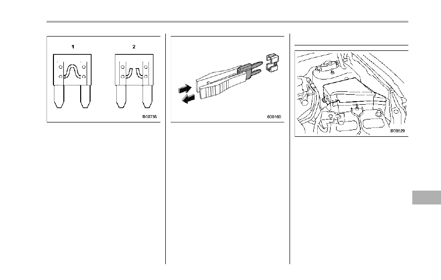
1)
Good
2)
Blown
If any lights, accessories or other electrical
controls do not operate, inspect the
corresponding fuse. If a fuse has blown,
replace it.
1. Turn the ignition switch to the “LOCK”
position and turn off all electrical acces-
sories.
2. Remove the cover.
3. Determine which fuse may be blown.
Look at the back side of each fuse box
cover and refer to “Fuses and circuits”
F12-9.
4. Pull out the fuse with the fuse puller.
5. Inspect the fuse. If it has blown,
replace it with a spare fuse of the same
rating.
6. If the same fuse blows again, this
indicates that its system has a problem.
Contact your SUBARU dealer for repairs.
Main fuse
Main fuse box
The main fuses are designed to melt
during an overload to prevent damage to
the wiring harness and electrical equip-
ment. Check the main fuses if any
electrical component fails to operate (ex-
cept the starter motor) and other fuses are
good. A melted main fuse must be
replaced. Use only replacements with the
same specified rating as the melted main
fuse. If a main fuse blows after it is
replaced, have the electrical system
checked by your nearest SUBARU dealer.
Maintenance and service
11-35
11-36
Maintenance and service
Installation of accessories
Always consult your SUBARU dealer
before installing fog lights or any other
electrical equipment in your vehicle. Such
accessories may cause the electronic
system to malfunction if they are incor-
rectly installed or if they are not suited for
the vehicle.
Replacing bulbs
WARNING
Bulbs may become very hot while
illuminated. Before replacing bulbs,
turn off the bulbs and wait until the
bulbs cool down. Otherwise, there is
a risk of sustaining a burn injury.
CAUTION
Replace any bulb only with a new
bulb of the specified wattage. Using
a bulb of different wattage could
result in a fire. For the specified
wattage of each bulb, refer to “Bulb
chart” F12-12.
& Headlights (models with HID
headlights)
WARNING
High-intensity-discharge (HID) bulbs
are used for the low beams of the
headlights. These HID bulbs use an
extremely high voltage. To avoid the
risk of an electric shock that could
result in serious injury, observe the
following precautions.
. Do not replace any headlight
bulbs (both low beam and high
beam) by yourself.
. Do not remove/restore the head-
light assemblies by yourself.
. Do not remove any headlight-
assembly components by your-
self.
For replacement, contact your
SUBARU dealer.
& Headlights (models without
HID headlights)
CAUTION
Halogen headlight bulbs become
very hot while in use. If you touch
the bulb surface with bare hands or
greasy gloves, fingerprints or
grease on the bulb surface will
develop into hot spots, causing the
bulb to break. If there are finger
prints or grease on the bulb surface,
wipe them away with a soft cloth
moistened with alcohol.
NOTE
. If headlight aiming is required, con-
sult your SUBARU dealer for proper
adjustment of the headlight aim.
. It may be difficult to replace the
bulbs. Have the bulbs replaced by your
SUBARU dealer if necessary.
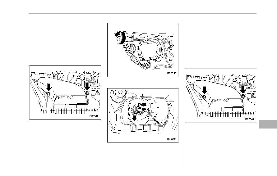
! Low beam light bulbs (right-hand
side)
1. Use a screwdriver to undo the clips on
the air intake duct, then remove the air
intake duct.
2. Use a screwdriver to remove the bulb
cover.
3. Disconnect the electrical connector.
4. Remove the retainer spring.
5. Replace the bulb, then set the retainer
spring securely.
6. Reconnect the electrical connector.
7. Install the bulb cover with the fixing
screws.
8. Install the air intake duct with the clips.
NOTE
Contact your SUBARU dealer for the
bulb replacement of the left-hand side.
! High beam light bulbs
Right-hand side
1. Use a screwdriver to undo the clips on
the air intake duct, then remove the air
intake duct (right-hand side).
Maintenance and service
11-37
– CONTINUED –
11-38
Maintenance and service
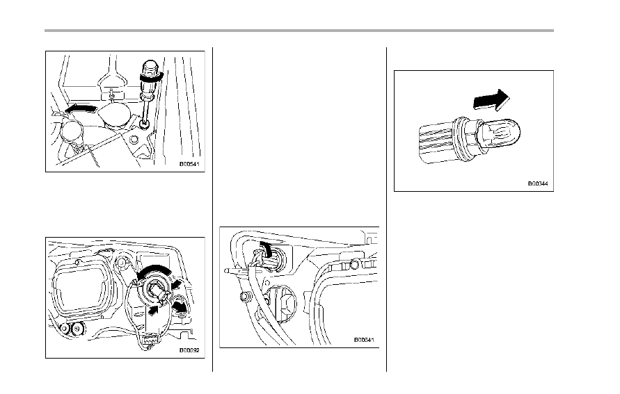
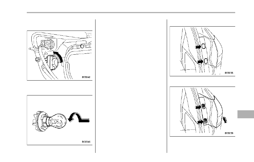
Left-hand side
2. Use a screwdriver to remove the
secured clip of the washer tank. To make
it easy to access the bulb, move the
washer tank to the horizontal direction
(left-hand side).
3. Disconnect the electrical connector
from the bulb.
4. Remove the bulb from the headlight
assembly by turning it counterclockwise.
5. Replace the bulb with new one. At this
time, use care not to touch the bulb
surface.
6. Reconnect the electrical connector.
7. To install the bulb to the headlight
assembly, turn it clockwise until it clicks.
8. Install the air intake duct with clips
(right-hand side).
9. Set the washer tank to the original
place and secure it by clip (left-hand side).
& Parking light (right-hand
side)
1. Remove the bulb socket from the
headlight assembly by turning it counter-
clockwise.
2. Pull the bulb out of the socket.
3. Install a new bulb.
4. Set the bulb socket into the headlight
assembly and turn it clockwise until it
locks.
NOTE
Contact your SUBARU dealer for the
bulb replacement of the left-hand side.
& Front turn signal light (right-
hand side)
1. Remove the bulb socket from the
headlight assembly by turning it counter-
clockwise.
2. Remove the bulb from the socket by
pushing it and turning counterclockwise.
3. Install a new bulb.
4. Set the bulb socket into the headlight
assembly and turn it clockwise until it
locks.
NOTE
Contact your SUBARU dealer for the
bulb replacement of the left-hand side.
& Front fog light
It may be difficult to replace the bulbs.
Have the bulbs replaced by your SUBARU
dealer if necessary.
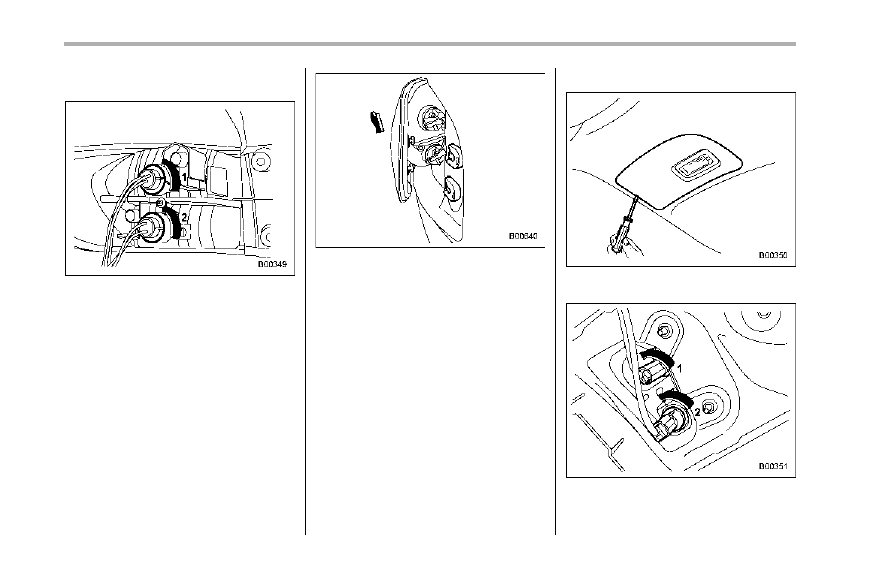
& Rear combination lights
1. Remove the two covers by inserting
the tip of a flat-head screwdriver.
2. Using a Phillips screwdriver, remove
the upper and lower screws. Then, slide
Maintenance and service
11-39
– CONTINUED –
11-40
Maintenance and service
the rear combination light assembly rear-
ward and remove it from the vehicle.
1)
Stop light/Tail light
2)
Rear turn signal light
3. Remove the bulb holder from the rear
combination light assembly by turning it
counterclockwise.
4. Remove the bulb from the socket by
pushing it and turning counterclockwise.
5. Install a new bulb.
6. Set the bulb holder into the rear
combination light assembly and turn it
clockwise until it locks.
7. Reinstall the rear combination light
assembly by sliding the two-pronged part
of the combination light assembly securely
to each holder of the vehicle side.
8. Tighten the two mounting screws, and
then close the covers.
& Backup light/Tail light
1. Use a flat-head screwdriver to remove
the light cover from the rear gate trim.
1)
Tail light
2)
Backup light
2. Turn the bulb socket counterclockwise
and remove it.
3. Pull the bulb out of the bulb socket and
replace it with a new one.
4. Install the bulb socket by turning it
clockwise.
5. Install the light cover on the rear gate.
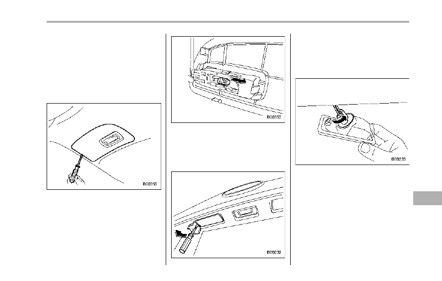
& Rear gate light
1. Use a flat-head screwdriver to remove
the rear gate light assembly from the rear
gate trim.
2. Pull the bulb out of the bulb socket and
replace it with a new one.
3. Install the rear gate light assembly on
the rear gate.
& License plate light
1. Wrap a flat-head screwdriver in vinyl
tape or cloth, insert it into the gap between
the license plate light assembly and the
rear gate.
2. Carefully pry the light assembly to
remove it.
3. Remove the bulb socket from the
license plate light assembly by turning it
counterclockwise.
Maintenance and service
11-41
– CONTINUED –
11-42
Maintenance and service
4. Pull the bulb out of the socket. Install a
new bulb.
5. Set the bulb socket into the license
plate light assembly and turn it clockwise
until it locks.
6. Reinstall the license plate light assem-
bly to the rear gate.
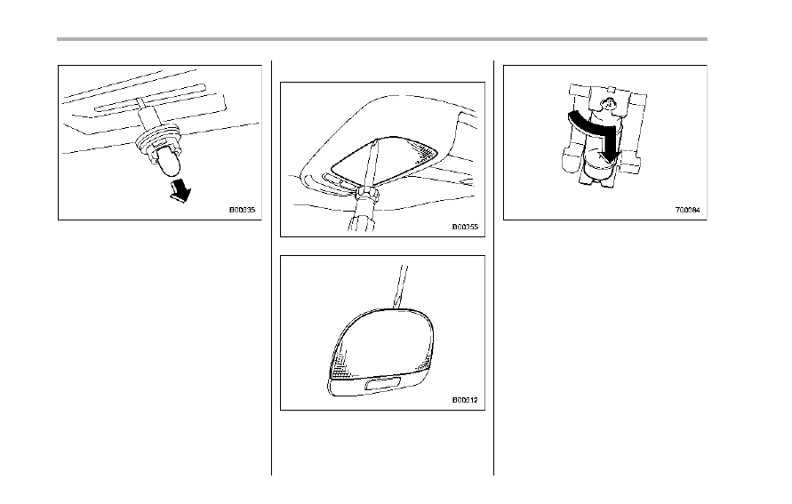
& Dome light
Models with Rear Seat Entertainment
Models without Rear Seat Entertainment
1. Remove the lens by prying the edge of
the lens with a flat-head screwdriver.
2. Turn the bulb until the flat surfaces at
its ends are aligned vertically. Pull the bulb
straight downward to remove it.
3. Install a new bulb.
4. Reinstall the lens.
Нет комментариевНе стесняйтесь поделиться с нами вашим ценным мнением.
Текст