Subaru XV Crosstrek (2016 year). Manual — part 35

Specifications/Specifications
& Tires
! U.S.-spec. models and Canada-spec. models
Tire size
P195/65R15 89H
P205/55R16 89V
P205/50R17 88V
P225/55R17 95H
Wheel size
15
6 6 J
16
6 6
1
/
2
J
17
6 7 JJ*
1
17
6 7 J*
2
17
6 7 J
Pressure
Front
35 psi (240 kPa, 2.4 kgf/cm
2
)
32 psi (220 kPa, 2.2 kgf/cm
2
)
CVT models 33 psi (230 kPa, 2.3 kgf/cm
2
)
MT models
32 psi (220 kPa, 2.2 kgf/cm
2
)
Rear
33 psi (230 kPa, 2.3 kgf/cm
2
)
30 psi (210 kPa, 2.1 kgf/cm
2
)
CVT models 32 psi (220 kPa, 2.2 kgf/cm
2
)
MT models
30 psi (210 kPa, 2.1 kgf/cm
2
)
Temporary
spare tire
Size
T135/80 D16
T145/90 D16
Pressure
60 psi (420 kPa, 4.2 kgf/cm
2
)
Wheel nut tightening
torque
89 lbf·ft (120 N·m, 12 kgf·m)*
3
*1:
“SPORT” and “SPORT-Ltd” models
*2: Other vehicle models
*3: This torque is equivalent to applying approximately 88 to 110 lbf (40 to 50 kgf) at the end of the wheel nut wrench. If you have tightened the wheel
nuts by yourself, have the tightening torque checked at the nearest automotive service facility as soon as possible. For the wheel nut tightening
procedure, refer to
“Changing a flat tire” F9-6.
12-8

! Other models
Tire size
P205/55R16 89V
P205/50R17 88V
225/55R17 97V
Wheel size
16
6 6 1/2 J
17
6 7 J
17
6 7 J
Pressure
Front
35 psi (240 kPa, 2.4 kgf/cm
2
)
32 psi (220 kPa, 2.2 kgf/cm
2
)
32 psi (220 kPa, 2.2 kgf/cm
2
)
Rear
33 psi (230 kPa, 2.3 kgf/cm
2
)
30 psi (210 kPa, 2.1 kgf/cm
2
)
30 psi (210 kPa, 2.1 kgf/cm
2
)
Temporary spare
tire
Size
P205/55R16
P205/50R17
185/65R17
Pressure
35 psi (240 kPa, 2.4 kgf/cm
2
)
32 psi (220 kPa, 2.2 kgf/cm
2
)
42 psi (290 kPa, 3.0 kgf/cm
2
)
Wheel nut tightening torque
73.8 lbf·ft (100 N·m, 10.2 kgf·m)
& Brake disc
If you need information on the usage limit value of brake discs and the method for measuring them, we recommend that you consult
your SUBARU dealer.
Specifications/Specifications
12-9
Specifications/Fuses and circuits
Fuses and circuits
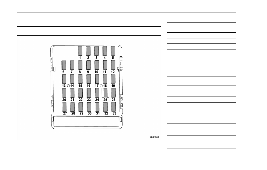
& Fuse panel located in the passenger compartment
Fuse
panel
Fuse
rating
Circuit
1
20A
. Trailer hitch connector
2
15A
—
3
15A
. Door locking
4
10A
. Front wiper deicer relay
5
10A
. Combination meter
. Clock
6
7.5A
. Remote control rear
view mirrors
. Seat heater relay
7
15A
. Combination meter
. Integrated unit
8
10A
. Stop light
9
15A
. Front wiper deicer
10
7.5A
. Power supply (battery)
11
7.5A
. Turn signal unit
12
15A
. Transmission
control
unit
. Engine control unit
. Integrated unit
13
20A
. Accessory power outlet
(center console)
. AC110V (If installed)
14
15A
. Parking light
. Tail light
. Rear combination light
12-10

Fuse
panel
Fuse
rating
Circuit
15
10A
. Luggage light
. Clock
16
7.5A
. Illumination
17
15A
. Seat heaters
18
10A
. Backup light
19
7.5A
. Power window relay
. Radiator main fan relay
20
10A
. Accessory power outlet
(instrument panel)
21
10A
. Starter relay
22
7.5A
. Air conditioner
. Rear window defogger
relay coil
23
Empty
24
10A
. Audio unit
. Clock
25
15A
. SRS airbag system
26
Empty
27
15A
. Blower fan
28
15A
. Blower fan
29
15A
. Fog light
30
Empty
31
7.5A
. Auto air conditioner unit
. Integrated unit
Fuse
panel
Fuse
rating
Circuit
32
7.5A
. Clutch switch
. Steering lock control
unit
33
7.5A
. Vehicle Dynamics Con-
trol unit
Specifications/Fuses and circuits
– CONTINUED –
12-11
Specifications/Fuses and circuits
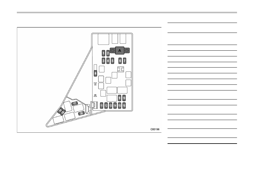
& Fuse panel located in the engine compartment
A)
Main fuse
Fuse
panel
Fuse
rating
Circuit
1
30A
. ABS unit
. Vehicle Dynamics Con-
trol unit
2
25A
. Main fan (cooling fan)
3
25A
. Sub fan (cooling fan)
4
Empty
5
Empty
6
30A
. Headlight (low beam)
7
15A
. Headlight (high beam)
8
20A
. Back-up
9
15A
. Horn
10
25A
. Rear window defogger
. Mirror heater
11
15A
. Fuel pump
12
20A
. Continuously
variable
transmission control unit
13
7.5A
. Engine control unit
14
15A
. Turn and hazard warn-
ing flasher
15
15A
. Tail and illumination re-
lay
16
7.5A
. Alternator
12-12

Fuse
panel
Fuse
rating
Circuit
17
Empty
18
10A
. Telematics
19
15A
. Headlight (low beam –
right hand)
20
15A
. Headlight (low beam –
left hand)
Specifications/Fuses and circuits
12-13
Specifications/Bulb chart
Bulb chart
& Safety precautions
WARNING
. Bulbs may become very hot while
illuminated. Before replacing
bulbs, turn off the lights and wait
until the bulbs cool down. Other-
wise, there is a risk of sustaining
a burn injury.
. For models with HID low beam
headlights, observe the following
precautions. Not doing so carries
the risk of an electric shock that
could result in serious injury
because the HID bulbs use an
extremely high voltage.
– Do not replace any headlight
bulbs (both low beam and
high beam) by yourself.
– Do not remove/restore the
headlight assemblies by your-
self.
– Do not remove any headlight-
assembly components by
yourself.
For replacement, contact your
SUBARU dealer.
CAUTION
Replace any bulb only with a new
bulb of the specified wattage. Using
a bulb of different wattage could
result in a fire.
12-14
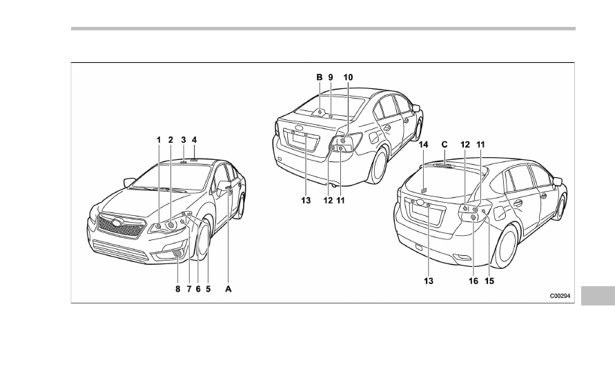
& Bulb chart
NOTE
Lights A, B and C are the LED (Light Emitting Diode) type. Consult your SUBARU dealer for replacement.
Specifications/Bulb chart
– CONTINUED –
12-15
Specifications/Bulb chart
Wattage
Bulb No.
1)
High beam headlight
12V-60W
HB3
2)
Low beam headlight
Models with HID light
12V-35W
D2R
Models with halogen light
12V-55W
H11
3)
Map light
12V-8W
–
4)
Dome light
12V-8W
–
5)
Front side marker light
12V-5W
W5W
6)
Parking light
12V-5W
W5W
7)
Front turn signal light
12V-21W
WY21W
8)
Front fog light
Models without steering responsive fog lights system
12V-24W
PSX24W
Models with steering responsive fog lights system
12V-55W
H11
9)
Trunk light (4-door)
12V-5W
W5W
10) Stop light/Tail and rear side marker light (4-door)
12V-21/5W
W21/5W
11)
Rear turn signal light
12V-21W
WY21W
12) Backup light
12V-16W
W16W
13) License plate light
12V-5W
W5W
14) Cargo area light (5-door)
12V-5W
–
15) Rear side marker light (5-door)
12V-5W
W5W
16) Stop light/Tail light (5-door)
12V-21/5W
W21/5W
A)
Side turn signal light (if equipped)
–
–
B)
High-mounted stop light (4-door)
–
–
C)
High-mounted stop light (5-door)
–
–
12-16
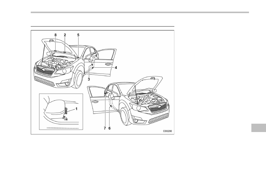
Vehicle identification
1)
Vehicle identification number (under the
floor carpet of the right-hand front seat)
2)
Emission control label
3)
Tire inflation pressure label
4)
Certification label
5)
Vehicle identification number plate
6)
Model number label
7)
Fuel label
8)
Air conditioner label
Specifications/Vehicle identification
12-17

For U.S.A. . . . . . . . . . . . . . . ...
13-2
Tire information . . . . . . . . . . . . ..
13-2
Tire labeling . . . . . . . . . . . . . ...
13-2
Recommended tire inflation pressure. . . . ..
13-4
Glossary of tire terminology . . . . . . . ...
13-5
Tire care
– maintenance and safety
practices. . . . . . . . . . . . . .
13-10
Vehicle load limit
– how to determine. . . . 13-10
Determining compatibility of tire and vehicle
load capacities . . . . . . . . . . . ...
13-13
Adverse safety consequences of overloading
on handling and stopping and on tires . . ...
13-14
Steps for Determining Correct Load Limit. . .
13-14
Uniform tire quality grading standards . . ..
13-15
Treadwear . . . . . . . . . . . . . ...
13-15
Traction AA, A, B, C. . . . . . . . . . .
13-15
Temperature A, B, C. . . . . . . . . . .
13-15
Reporting safety defects (U.S.A.) . . . . ...
13-16
Supplement . . . . . . . . . . . . . ..
13-17
Declaration of conformity with FCC rules . . .
13-17
Consumer information and Reporting safety defects
13

Consumer information and Reporting safety defects/For U.S.A.
For U.S.A.
The following information has been
compiled according to Code of
Federal Regulations
“Title 49, Part
575
”.
Tire information
& Tire labeling
Many markings (e.g. Tire size, Tire
Identification Number or TIN) are
placed on the sidewall of a tire by
tire manufacturers. These markings
can provide you with useful infor-
mation on the tire.
! Tire size
Your vehicle comes equipped with
P-Metric tire size. It is important to
understand the sizing system in
selecting the proper tire for your
vehicles. Here is a brief review of
the tire sizing system with a break-
down of its individual elements.
! P Metric
With the P-Metric system, Section
Width is measured in millimeters.
To convert millimeters into inches,
divide by 25.4. The Aspect Ratio
(Section Height divided by Section
Width) helps provide more dimen-
sional information about the tire
size.
Example:
(1)
P = Certain tire type used on
light duty vehicles such as passen-
ger cars
(2)
Section Width in millimeters
(3)
Aspect Ratio (= section height
7 section width).
(4)
R = Radial Construction
(5)
Rim diameter in inches
! Load and Speed Rating De-
scriptions
The load and speed rating descrip-
tions will appear following the size
designation.
They provide two important facts
about the tire. First, the number
designation is its load index. Sec-
ond, the letter designation indicates
the tire
’s speed rating.
13-2
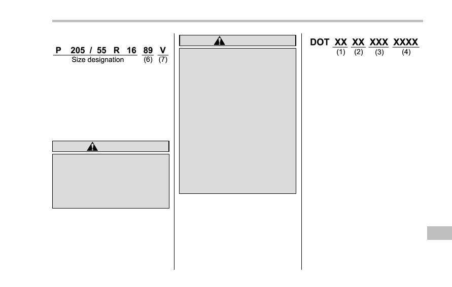
Example:
(6)
Load Index: A numerical code
which specifies the maximum load
a tire can carry at the speed
indicated by its speed symbol, at
maximum inflation pressure.
For example,
“90” means 1,323 lbs
(600 kg),
“89” means 1,278 lbs (580
kg).
WARNING
Load indices apply only to the
tire, not to the vehicle. Putting
a load rated tire on any vehicle
does not mean the vehicle can
be loaded up to the tire
’s rated
load.
(7)
Speed Rating: An alphabetical
system describing a tire
’s capability
to travel at established and prede-
termined speeds.
For example,
“V” means 149 mph
(240 km/h)
WARNING
.
Speed ratings apply only to
the tire, not to the vehicle.
Putting a speed rated tire on
any vehicle does not mean
the vehicle can be operated
at the tire
’s rated speed.
.
The speed rating is void if
the tires are worn out, da-
maged, repaired, retreaded,
or otherwise altered from
their original condition. If
t i r e s a r e r e p a i r e d , r e -
treaded, or otherwise al-
tered, they may not be sui-
table for original equipment
tire designed loads and
speeds.
! Tire Identification Number (TIN)
Tire Identification Number (TIN) is
marked on the intended outboard
sidewall. The TIN is composed of
four groups. Here is a brief review
of the TIN with a breakdown of its
individual elements.
(1)
Manufacturer
’s Identification
Mark
(2)
Tire Size
(3)
Tire Type Code
(4)
Date of Manufacture
The first two figures identify the
week, starting with
“01” to represent
the first full week of the calendar
year; the second two figures repre-
sent the year. For example, 0101
means the 1st week of 2001.
! Other markings
The following makings are also
placed on the sidewall.
! Maximum permissible infla-
tion pressure
The maximum cold inflation pres-
sure to which this tire may be
inflated. For example,
“300 kPa
(44 PSI) MAX. PRESS
”
Consumer information and Reporting safety defects/Tire information
– CONTINUED –
13-3
Consumer information and Reporting safety defects/Tire information
! Maximum load rating
The load rating at the maximum
permissible weight load for this tire.
For example,
“MAX. LOAD 580 kg
(1279 LBS) @ 300 kPa (44 PSI)
MAX. PRESS.
”
WARNING
Maximum load rating applies
only to the tire, not to the
vehicle. Putting a load rated
tire on any vehicle does not
mean the vehicle can be
loaded up to the tire
’s rated
load.
! Construction type
Applicable construction of this tire.
For example,
“TUBELESS STEEL
BELTED RADIAL
”
! Construction
The generic name of each cord
material used in the plies (both
sidewall and tread area) of this tire.
For example,
“PLIES: TREAD 2
STEEL + 2 POLYESTER SIDE-
WALL 2 POLYESTER
”
! Uniform Tire Quality Grading
(UTQG)
For details, refer to
“Uniform tire
quality grading standards
” F13-15
.
& Recommended tire inflation
pressure
! Recommended cold tire infla-
tion pressure
For recommended cold tire inflation
pressure for your vehicle
’s tires,
refer to
“Tires” F12-8
.
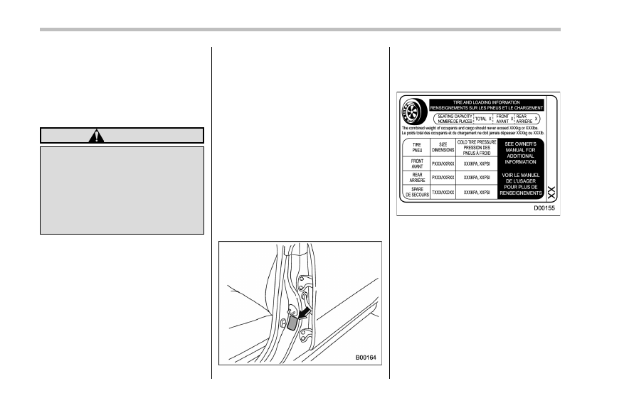
! Vehicle placard
The vehicle placard is attached to
the driver
’s side door pillar.
Example:
The vehicle placard shows original
tire size, recommended cold tire
inflation pressure on each tire at
maximum loaded vehicle weight,
seating capacity and loading infor-
mation.
! Adverse safety consequences
of under-inflation
Driving at high speeds with exces-
sively low tire pressures can cause
the tires to flex severely and to
rapidly become hot. A sharp in-
13-4

crease in temperature could cause
tread separation, and failure of the
tire(s). Possible resulting loss of
vehicle control could lead to an
accident.
! Measuring and adjusting air
pressure to achieve proper in-
flation
Check and, if necessary, adjust the
pressure of each tire (including the
spare) at least once a month and
before any long journey. Check the
tire pressures when the tires are
cold. Use a pressure gauge to
adjust the tire pressures to the
specific values. Driving even a
short distance warms up the tires
and increases the tire pressures.
Also, the tire pressures are affected
by the outside temperature. It is
best to check tire pressure out-
doors before driving the vehicle.
When a tire becomes warm, the air
inside it expands, causing the tire
pressure to increase. Be careful not
to mistakenly release air from a
warm tire to reduce its pressure.
& Glossary of tire terminology
.
Accessory weight
The combined weight (in excess of
those standard items which may be
replaced) of automatic transmis-
sion, power steering, power brakes,
power windows, power seats, radio,
and heater, to the extent that these
items are available as factory-in-
stalled equipment (whether in-
stalled or not).
.
Bead
The part of the tire that is made of
steel wires, wrapped or reinforced
by ply cords and that is shaped to fit
the rim.
.
Bead separation
A breakdown of the bond between
components in the bead.
.
Bias ply tire
A pneumatic tire in which the ply
cords that extend to the beads are
laid at alternate angles substantially
less than 90 degrees to the center-
line of the tread.
.
Carcass
The tire structure, except tread and
sidewall rubber which, when in-
flated, bears the load.
.
Chunking
The breaking away of pieces of the
tread or sidewall.
.
Cold tire pressure
The pressure in a tire that has been
driven less than 1 mile or has been
standing for three hours or more.
.
Cord
The strands forming the plies in the
tire.
.
Cord separation
The parting of cords from adjacent
rubber compounds.
.
Cracking
Any parting within the tread, side-
wall, or inner liner of the tire
extending to cord material.
.
Curb weight
The weight of a motor vehicle with
standard equipment including the
maximum capacity of fuel, oil and
coolant, and if so equipped, air
conditioning and additional weight
optional engine.
Consumer information and Reporting safety defects/Tire information
– CONTINUED –
13-5

Consumer information and Reporting safety defects/Tire information
.
Extra load tire
A tire designed to operate at higher
loads and higher inflation pressure
than the corresponding standard
tire.
.
Groove
The space between two adjacent
tread ribs.
.
Innerliner
The layer(s) forming the inside sur-
face of a tubeless tire that contains
the inflating medium within the tire.
.
Innerliner separation
The parting of the innerliner from
cord material in the carcass.
.
Intended outboard sidewall
(1)
The sidewall that contains a
whitewall, bears white lettering
or bears manufacturer, brand,
and/or model name molding that
is higher or deeper than the
same molding on the other side-
wall of the tire, or
(2)
The outward facing sidewall
of an asymmetrical tire that has
a particular side that must al-
ways face outward when mount-
ing on a vehicle.
.
Light truck (LT) tire
A tire designated by its manufac-
turer as primarily intended for use
on lightweight trucks or multipur-
pose passenger vehicles.
.
Load rating
The maximum load that a tire is
rated to carry for a given inflation
pressure.
.
Maximum inflation pressure
The maximum cold inflation pres-
sure to which a tire may be inflated.
.
Maximum load rating
The load rating for a tire at the
maximum permissible inflation
pressure for that tire.
.
Maximum loaded vehicle weight
The sum of:
(a)
Curb weight
(b)
Accessory weight
(c)
Vehicle capacity weight
(d)
Production options weight
.
Maximum permissible inflation
pressure
The maximum cold inflation pres-
sure to which a tire may be inflated.
.
Measuring rim
The rim on which a tire is fitted for
physical dimension requirements.
.
Normal occupant weight
150 lbs (68 kg) times the number of
occupants specified in the second
column of Table 1 that is appended
to the end of this section.
.
Occupant distribution
Distribution of occupants in a vehi-
cle as specified in the third column
of Table 1 that is appended to the
end of this section.
.
Open splice
Any parting at any junction of tread,
sidewall, or innerliner that extends
to cord material.
.
Outer diameter
The overall diameter of an inflated
new tire.
.
Overall width
The linear distance between the
exteriors of the sidewalls of an
inflated tire, including elevations
due to labeling, decorations, or
protective bands or ribs.
13-6
Нет комментариевНе стесняйтесь поделиться с нами вашим ценным мнением.
Текст