Suzuki Grand Vitara JB627. Service manual — part 149
3B-38 Differential: Rear
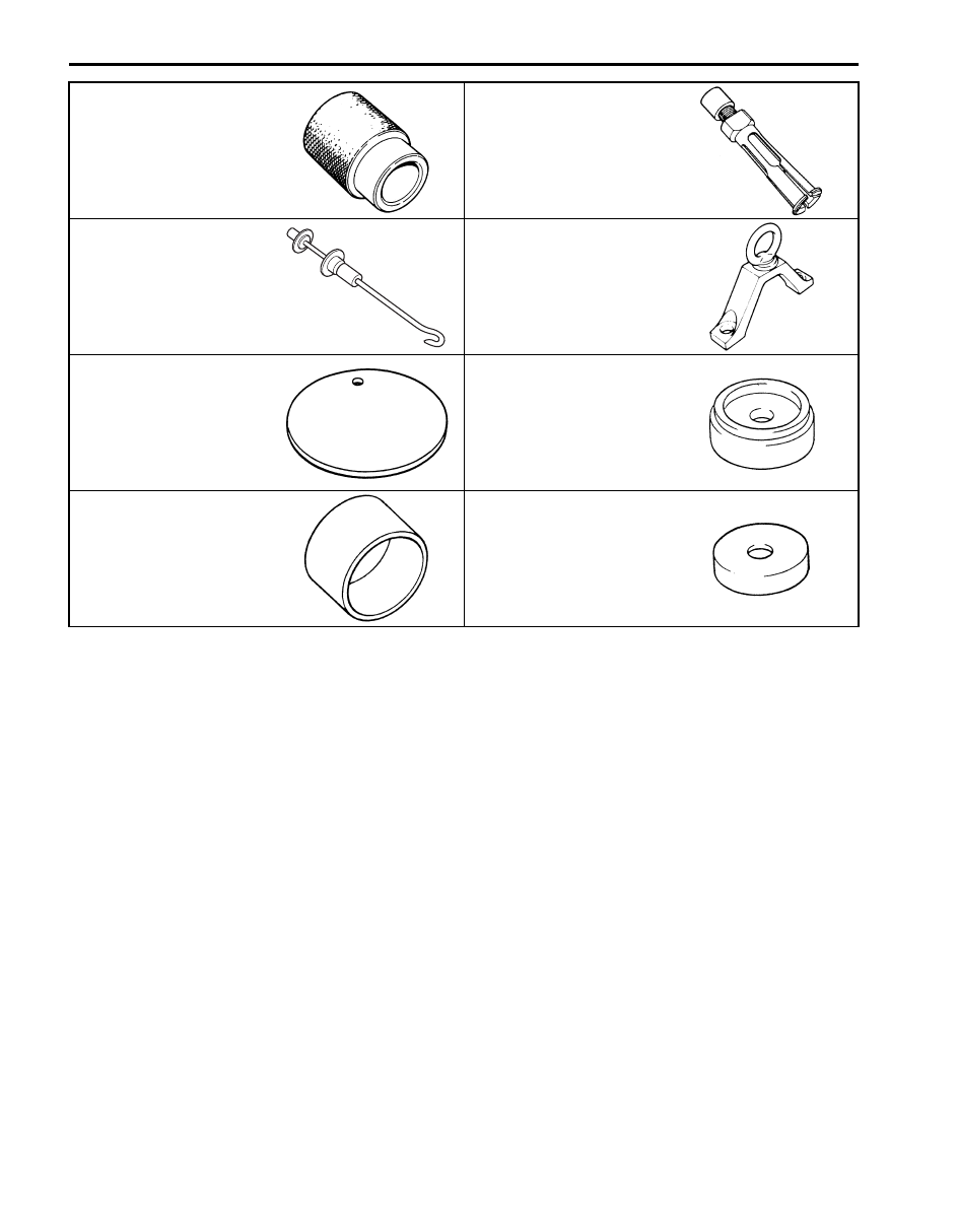
09940–53111
09941–64511
Differential side bearing
installer
Bearing and oil seal remover
(30 mm Min.)
09942–15511
09943–17912
Sliding hammer
Wheel hub remover
09951–16070
09951–16090
Shim adjuster attachment
Oil seal installer
09951–18210
09951–46010
Oil seal remover & installer
No. 2
Drive shaft oil seal installer
Transfer: 3C-1
Driveline / Axle
Transfer
Precautions
Transfer Warning
S6JB0B3300001
WARNING
!
This transfer has a center differential.
When testing with 2-wheel chassis
dynamometer or speedometer tester (which
tester roller is driven by vehicle wheels), be
sure to make the vehicle as rear wheel drive
or as front wheel drive temporarily as
follows.
Otherwise, front wheels drive rear wheels or
vise-versa and personal injury may result.
1) Remove front propeller shaft or rear propeller shaft
referring to “Propeller Shaft Removal and Installation
in Section 3D”.
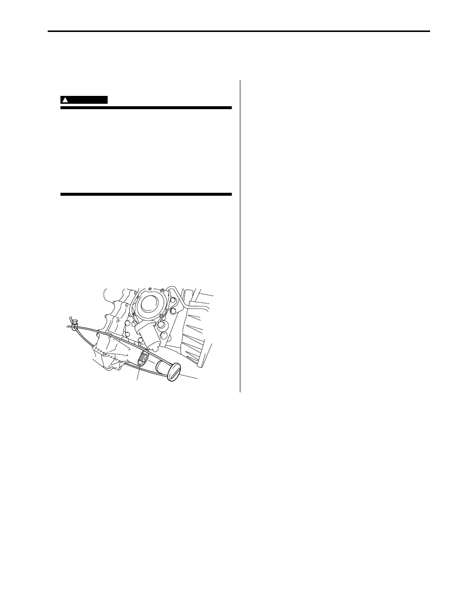
2) Install special tool (cap) to flange yoke cover hole
(front or rear) of transfer (1) and fix it to transfer or
hook with string to prevent oil leakage from transfer.
Special tool
(A): 09928–36510
3) Pour specified oil into transfer up to lever plug hole if
front propeller shaft is removed.
4) Shift transfer to 4H-lock position by turning transfer
switch.
Precautions in Diagnosing Trouble
S6JB0B3300002
• Do not disconnect the following parts before
confirming diagnostic information (DTC, etc.) stored in
4WD control module memory. These actions will
erase memorized information in 4WD control module
memory.
– Disconnection of coupler from 4WD control module
– Disconnection of battery cable from battery
– Disconnection of ground wire harness of 4WD
control module
– Disconnect main fuse from fuse box
• Diagnostic information stored in 4WD control module
memory can be cleared as well as checked by using
SUZUKI scan tool. Before using scan tool, read its
Operator’s (Instruction) Manual carefully to have good
understanding as to what functions are available and
how to use it.
• Be sure to read “Precautions for Electrical Circuit
Service:” before inspection and observe what is
written there.
General Description
Transfer Description
S6JB0B3301001
The aluminum transfer case directly connected to the back of the transmission contains input gear, counter gear, rear
output shaft, front output shaft, center differential, drive chain and their accompanying gears, hubs, sleeves, fork, etc.
The center differential is installed in the transfer. With the torque induction type LSD used in the center differential, the
effect of LSD works when a rotation difference between front and rear wheels is occurring.
The transfer has such a selective mechanism as to enable the shift actuator to make selection of high speed (direct
connection with transmission output: main shaft), low speed (speed reduction by input gear, counter gear and low
gear) or neutral by way of the reduction shift sleeve located between the input gear and low gear, and selection of
center differential lock or not by way of the differential lock clutch sleeve located at the center of the rear output shaft.
The case has an oil pump to provide proper lubrication.
(A)
1
I5JB0A331107-03
3C-2 Transfer:
4WD Control System Description
S6JB0B3301003
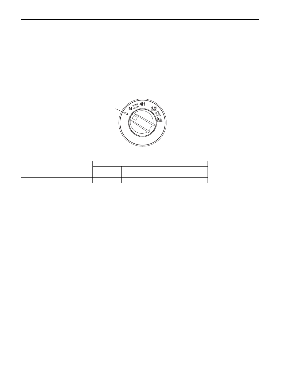
Transfer Shift Control
The 4WD control module controls the transfer shift actuator based on the signal from the transfer switch so that the
transfer is shifted to the selected position (4H, 4H-lock, N or 4L-lock). (Shifting to the N position requires that the
switch to “” position (1) keep it there for about 10 seconds then turn it to “N” position.)
The transfer actuator consists of the actuator motor and the actuator motor position switch. The 4WD control module
detects the position of the actuator motor using the position switch and controls the actuator motor running / stopping
operation.
Also, the 4L/N switch and center differential lock switch that detect the each position of the High / Low shift fork and
the differential lock shift fork are installed the transfer assembly. The 4WD control module detects the transfer actual
shift position (4H, 4H-lock, N or 4L-lock) by the signals from the 4L/N switch and center differential lock switch as
follows.
Relationship of transfer shift position and switches
When the transfer shift actuator motor position detected by motor position switch and transfer actual shift position
detected by the above-mentioned switches match, the 4WD control module judges that the transfer shifting is
complete.
Retry Control
When 4WD control module cannot judge the shifting to the target position, it commands to retry the shifting up to 3
times. If retry shifting is not possible, previous shift position is restored and notify failure of the shifting with the
indicator and buzzer.
Indicator And Buzzer Operation
The 4WD control module output operation signal of the differential lock indicator, 4L indicator, N indicator and the
buzzer to BCM. Indicators and buzzer as follows in order to inform what state the transfer control system is.
Switch
Transfer shift position
4H
4H-lock
N
4L-lock
4L/N switch
OFF
OFF
ON
ON
Center differential lock switch
ON
OFF
ON
OFF
1
I5JB0A332002-01

Transfer: 3C-3
Operation
Condition
Indicator
Buzzer
Differential
lock
indicator
OFF
—
• Ignition switch is OFF.
• Transfer is at 4H/N position.
ON
—
• Within 2 seconds after ignition switch is turn ON (checking
indicator operation).
• Transfer is at 4H-lock/4L-lock position.
Flashes at 0.25
seconds for 3
times, at intervals
of 20 seconds.
Sounds at 1
second at
intervals of 20
seconds.
• The transfer shift position is different for transfer switch.
Flashes at
intervals of 0.25
seconds
continuously
—
• 4WD control module detects DTC of 4WD control system.
Flashes at
intervals of 0.5
seconds
continuously
—
• Transfer is shifting from 4H to 4H-lock.
• Transfer is shifting from 4H-lock to 4H.
• Transfer could not complete shifting to 4H-lock.
4L indicator
OFF
—
• Ignition switch is OFF.
• Transfer is at 4H-lock/N position.
ON
—
• Within 2 seconds after ignition switch is turn ON (checking
indicator operation).
• Transfer is at 4L-lock position.
Flashes at 0.25
seconds for 3
times, at intervals
of 20 seconds.
Sounds at 1
second at
intervals of 20
seconds.
• The transfer shift position is different for transfer switch.
Flashes at
intervals of 0.25
seconds
continuously
—
• 4WD control module detects DTC of 4WD control system.
Flashes at
intervals of 0.5
seconds
continuously
—
• Transfer is shifting from 4H-lock to 4L-lock.
• Transfer is shifting from 4L-lock to 4H-lock.
• Transfer could not complete shifting to 4L-lock.
N indicator
OFF
—
• Ignition switch is OFF.
• Transfer is at 4H/4H-lock/4L-lock position.
ON
—
• Within 2 seconds after ignition switch is turn ON (checking
indicator operation).
• Transfer is at N position.
Flashes at 0.25
seconds for 3
times, at intervals
of 20 seconds.
Sounds at 1
second at
intervals of 20
seconds.
• The transfer shift position is different for transfer switch.
Flashes at
intervals of 0.2
seconds
continuously
—
• 4WD control module detects DTC of 4WD control system.
Flashes at 0.5
seconds
continuously
—
• Transfer could not complete shifting to N.
—
—
Sounds at 0.2
seconds for 2
times, at intervals
of 3 seconds.
• Transfer is at N position.
Нет комментариевНе стесняйтесь поделиться с нами вашим ценным мнением.
Текст