Suzuki Grand Vitara JB627. Service manual — part 198

4F-31 Electronic Stability Program:
DTC Troubleshooting
DTC C1038: Steering Angle Sensor Detect Rolling Counter Failure from ESP
® Control Module
S6JB0B4604034
DTC Detecting Condition and Trouble Area
DTC Troubleshooting
Step
Action
Yes
No
1
Was “Electronic Stability Program Check” performed?
Go to Step 2
Go to “Electronic
Stability Program
Check”.
2
Check steering angle sensor power supply circuit
1) Check circuit fuses for steering angle sensor and its
circuit.
Is it good condition?
Go to Step 3.
Replace fuse and check
for short circuit to
ground.
3
Check steering angle sensor power supply circuit
1) Turn ignition switch to OFF position.
2) Disconnect steering angle sensor connector.
3) Check for proper connection to steering angle sensor
connector terminals at “E45-1”, “E45-2” and “E45-3”.
4) If OK, then measure voltage between connector terminal
“E45-3” and vehicle body ground.
Is it 10 – 14 V?
Go to Step 4.
“WHT” wire circuit open.
4
Check steering angle sensor power supply circuit
1) Measure voltage between connector terminal “E45-1”
and vehicle body ground with ignition switch turned ON.
Is it 10 – 14 V?
Go to Step 5.
“GRN/ORN” wire circuit
open.
5
Check steering angle sensor power supply circuit
1) Turn ignition switch to OFF position.
2) Measure resistance between connector terminal “E45-2”
and vehicle body ground.
Is resistance less than 2
Ω
?
Go to Step 6.
“BLK” wire circuit open
or high resistance.
6
Check steering angle sensor
1) Connect steering angle sensor connector.
2) Check steering angle sensor referring to “Steering Angle
Sensor On-Vehicle Inspection”.
Is it good condition?
Substitute a known-
good ESP
® hydraulic
unit / control module
assembly and check
DTC.
Replace steering angle
sensor.
DTC Detecting Condition
Trouble Area
ESP
® control module rolling counter failure is detected by
steering angle sensor.
• CAN communication circuit
• Steering angle sensor
• ESP
® control module
Step
Action
Yes
No
1
Was “Electronic Stability Program Check” performed?
Go to Step 2.
Go to “Electronic
Stability Program
Check”.
2
Check DTC
1) Connect scan tool to DLC with ignition switch turned
OFF.
2) Turn ignition switch ON and check DTC.
Is there any DTC(s) other than C1038 and C1090?
Go to applicable DTC
diagnosis flow for
troubleshooting.
Go to Step 3.

Electronic Stability Program: 4F-32
DTC C1039: Yaw Rate / G Sensor Assembly Internal Failure
S6JB0B4604035
DTC Detecting Condition and Trouble Area
DTC Troubleshooting
DTC C1040: Stability Control System Function Failure
S6JB0B4604036
DTC Detecting Condition and Trouble Area
DTC Troubleshooting
3
Check ESP
® control module
1) Turn ignition switch to OFF position.
2) Substitute a known-good steering angle sensor.
3) Calibrate steering angle sensors referring to “Sensor
4) Clear all DTC(s) and recheck DTC.
Is DTC C1038 still detected?
Substitute a known-
good ESP
® hydraulic
unit / control module
assembly and check
DTC.
Steering angle sensor
was malfunction.
Step
Action
Yes
No
DTC Detecting Condition
Trouble Area
Yaw rate / G sensor assembly internal failure is detected. • Yaw rate / G sensor assembly
• ESP
® control module
Step
Action
Yes
No
1
Was “Electronic Stability Program Check” performed?
Go to Step 2.
Go to “Electronic
Stability Program
Check”.
2
DTC check
1) Connect scan tool to DLC with ignition switch turned
OFF.
2) Turn ignition switch ON and check DTC.
Are DTC C1034 and/or C1073 detected?
Go to applicable DTC
diagnosis flow for
troubleshooting.
Go to Step 3.
3
Check sensor calibration
1) Calibrate yaw rate / G sensor assembly referring to
2) Clear all DTC(s) and recheck DTC.
Is DTC C1039 still detected?
Go to Step 4.
Yaw rate / G sensor
assembly calibration
was incompleted.
4
Check yaw rate / G sensor assembly
1) Check yaw rate / G sensor assembly referring to “Yaw
Rate / G Sensor Assembly On-Vehicle Inspection”.
Is it good condition?
Substitute a known-
good ESP
® hydraulic
unit / control module
assembly and check
DTC.
Replace yaw rate / G
sensor assembly.
DTC Detecting Condition
Trouble Area
Stability control is active for more than specified time
without yaw rate change.
• ESP
® control module
Step
Action
Yes
No
1
Was “Electronic Stability Program Check” performed
Go to Step 2.
Go to “Electronic
Stability Program
Check”.
2
Check DTC for ESP
®
1) Connect scan tool to DLC with ignition switch turned
OFF.
2) Turn ignition switch ON and check DTC for ESP
®.
Is there any DTC(s) other than C1040?
Go to applicable DTC
diagnosis flow for
troubleshooting.
Substitute a known-
good ESP
® hydraulic
unit / control module
assembly and check
DTC.
4F-33 Electronic Stability Program:
DTC C1041 / C1042 / C1043 / C1044 / C1045 / C1046 / C1051 / C1052 / C1053 / C1054 / C1055 / C1056:
Inlet Solenoid Circuit Failure, Outlet Solenoid Circuit Failure, Master Cylinder Cut Solenoid Circuit
Failure, Low Pressure Solenoid Circuit Failure
S6JB0B4604015
DTC C1041 / C1045 / C1051 / C1055: Right-Front / Left-Front / Right-Rear / Left-Rear Inlet Solenoid
Circuit Failure
DTC C1042 / C1046 / C1052 / C1056: Right-Front / Left-Front / Right-Rear / Left-Rear Outlet Solenoid
Circuit Failure
DTC C1043 / C1044: Master Cylinder Cut Solenoid Circuit No. 1 / No. 2 Failure
DTC C1053 / C1054: Low Pressure Solenoid Circuit No. 1 / No. 2 Failure
DTC C1057: ESP
® (ABS) control module power supply circuit failure
S6JB0B4604016
®) Control Module Power Supply Circuit Failure in Section 4E”.
DTC C1061: Pump Motor and/or Motor Driver Circuit Failure
S6JB0B4604017
Refer to “DTC C1061: ABS Pump Motor and/or Motor Driver Circuit Failure in Section 4E”.
DTC C1063: Solenoid Valve Power Supply Driver Circuit Failure
S6JB0B4604018
Refer to “DTC C1063: Solenoid Valve Power Supply Driver Circuit Failure in Section 4E”.
DTC C1071: ESP
® (ABS) Control Module Internal Defect
S6JB0B4604019
®) control module Internal Detect in Section 4E”.
DTC C1073: Lost Communication With Yaw Rate / G Sensor Assembly
S6JB0B4604038
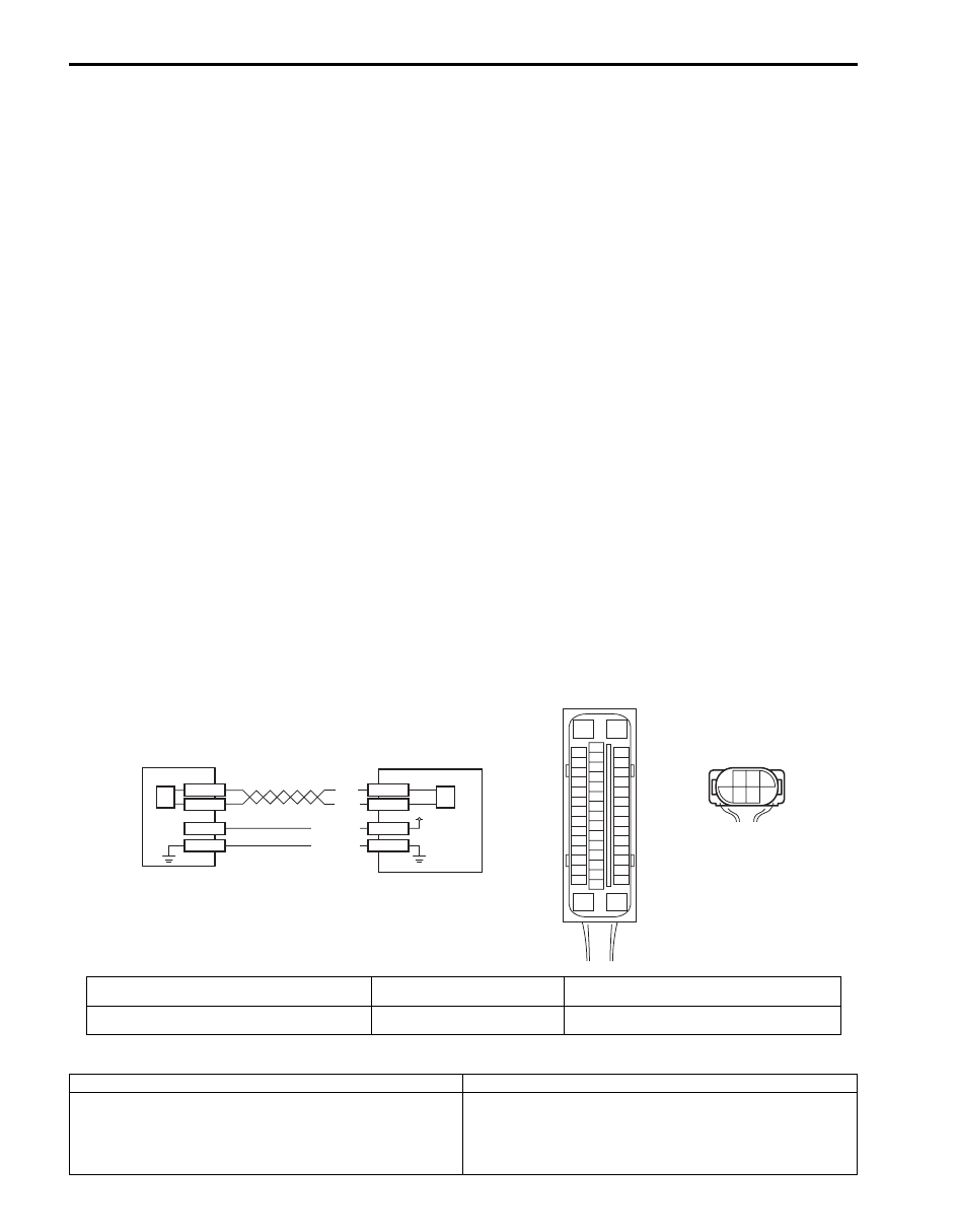
Wiring Diagram
DTC Detecting Condition and Trouble Area
[A]
E53
16
1
15
2
3
4
5
6
7
8
9
10
11
12
13
14
17
18
19
20
21
22
23
24
25
26
27
28
29
30
31
32
33
34
35
36
37
38
39
40
41
42
43
44
45
46
47
E53-29
E53-25
E53-37
E53-31
L39-3
L39-5
BLK
WHT
L39-2
L39-1
12V
PNK/GRN
PNK/WHT
[B]
L39
3
5
2 1
4
6
1
2
3
2
I6JB01460022-03
[A]: ESP
® control module connector (viewed from
terminal side)
1. Yaw rate / G sensor assembly
3. ESP
® hydraulic unit control module assembly
[B]: Yaw rate / G sensor assembly connector (viewed
from harness side)
2. CAN driver (for yaw rate / G
sensor assembly)
DTC Detecting Condition
Trouble Area
CAN line communication error in ESP
® control module
and yaw rate / G sensor assembly is detected.
• CAN communication circuit (for yaw rate / G sensor
assembly)
• Yaw rate / G sensor assembly
• ESP
® control module

Electronic Stability Program: 4F-34
DTC Troubleshooting
DTC C1075 / 1076 / 1077 / 1078: Steering Angle Sensor / Master Cylinder Pressure Sensor /
Longitudinal G Sensor / Lateral G Sensor in Yaw Rate / G Sensor Assembly Calibration Incomplete
S6JB0B4604039
DTC Detecting Condition and Trouble Area
Step
Action
Yes
No
1
Was “Electronic Stability Program Check” performed?
Go to Step 2.
Go to “Electronic
Stability Program
Check”.
2
DTC check for ESP
®
1) Connect scan tool to DLC with ignition switch turned
OFF.
2) Turn ignition switch ON and check DTC for ESP
®.
Is DTC C1057 detected?
Go to applicable DTC
diagnosis flow for
troubleshooting.
Go to Step 3.
3
Check each control module connectors
1) Check connection of connectors of all control modules
communicating by means of CAN (for yaw rate / G
sensor assembly).
2) Check DTC for ESP
®.
Is DTC C1073 detected?
Go to Step 4.
Check for intermittent
trouble referring to
“Intermittent and Poor
Connection Inspection
in Section 00”.
4
CAN communication circuit check
1) Turn ignition switch to OFF position.
2) Disconnect connectors of ESP
® control module and yaw
rate / G sensor assembly.
Is each CAN communication circuit between ESP
®
control
module and yaw rate / G sensor assembly opened, shorted
or high resistance?
Repair or replace the
CAN communication
line.
Go to Step 5.
5
Check yaw rate / G sensor assembly
1) Substitute a known-good yaw rate / G sensor assembly.
2) Connect connectors to ESP
® control module and yaw
rate / G sensor assembly.
3) Clear all DTC(s) and check DTC for ESP
®.
Is DTC C1073 still detected?
Substitute a known-
good ESP
® hydraulic
unit / control module
assembly and check
DTC.
Yaw rate / G sensor
assembly was
malfunction.
DTC Detecting Condition
Trouble Area
C1075:
Missing steering angle sensor calibration point data is
detected.
• Steering angle sensor
• Steering angle sensor calibration is incompleted
• ESP
® control module
C1076:
Master cylinder pressure sensor calibration is
incompleted.
• Master cylinder pressure sensor
• Master cylinder pressure sensor calibration is
incompleted
• ESP
® control module
C1077:
Longitudinal G sensor in yaw rate / G sensor assembly
calibration is incompleted. (4WD model)
• Yaw rate / G sensor assembly
• Longitudinal G sensor calibration is incompleted
• ESP
® control module
C1078:
Lateral G sensor in yaw rate / G sensor assembly
calibration is incompleted.
• Yaw rate / G sensor assembly
• Lateral G sensor calibration is incompleted
• ESP
® control module
Нет комментариевНе стесняйтесь поделиться с нами вашим ценным мнением.
Текст