Suzuki Grand Vitara JB627. Service manual — part 199

4F-35 Electronic Stability Program:
DTC Troubleshooting
DTC C1090: ECM Detect Rolling Counter Failure from ESP
® Control Module
S6JB0B4604040
DTC Detecting Condition and Trouble Area
DTC Troubleshooting
Step
Action
Yes
No
1
Was “Electronic Stability Program Check” performed?
Go to Step 2.
Go to “Electronic
Stability Program
Check”.
2
DTC check for ESP
®
1) Connect scan tool to DLC with ignition switch turned
OFF.
2) Turn ignition switch ON and check DTC for ESP
®.
Is there any DTC(s) other than C1075, C1076, C1077 and
C1078?
Go to applicable DTC
diagnosis flow for
troubleshooting.
Go to Step 3.
3
Check sensor calibration
1) Calibrate all sensors referring to “Sensor Calibration”.
2) Clear all DTC(s) and check DTC for ESP
®.
Is DTC C1075, C1076, C1077 and/or C1078 still detected?
DTC C1075: Replace
steering angle sensor.
DTC C1076: Replace
ESP
® hydraulic unit /
control module
assembly.
DTC C1077 / 1078:
Replace yaw rate / G
sensor assembly.
Calibration was
incompleted.
DTC Detecting Condition
Trouble Area
ESP
® control module rolling counter failure is detected by
ECM.
• CAN communication circuit
• ECM
• ESP
® control module
Step
Action
Yes
No
1
Was “Electronic Stability Program Check” performed?
Go to Step 2.
Go to “Electronic
Stability Program
Check”.
2
DTC check for ESP
®
1) Connect scan tool to DLC with ignition switch turned
OFF.
2) Turn ignition switch ON and check DTC for ESP
®.
Is there any DTC(s) other than C1038 and C1090?
Go to applicable DTC
diagnosis flow for
troubleshooting.
Go to Step 3.
3
DTC check for ECM
1) Check DTC for ECM.
Is DTC U0073 and/or DTC U0121 detected?
Go to applicable DTC
diagnosis flow for
troubleshooting.
Substitute a known-
good ESP
® hydraulic
unit / control module
assembly and check
DTC.

Electronic Stability Program: 4F-36
DTC C1091 / 1092 / 1093: ECM / TCM / 4WD Control Module Data in CAN Line Failure
S6JB0B4604041
DTC Detecting Condition and Trouble Area
DTC Troubleshooting
DTC U1073: Control Module Communication Bus Off
S6JB0B4604020
Refer to “DTC U1073: Control Module Communication Bus Off in Section 4E”.
DTC U1100: Lost Communication with ECM (Reception Error)
S6JB0B4604021
Refer to “DTC U1100: Lost Communication with ECM (Reception Error) in Section 4E”.
DTC Detecting Condition
Trouble Area
C1091:
ECM sent invalid signal to ESP
® control module.
• Engine control system
• ECM
• ESP
® control module
C1092:
TCM sent invalid signal to ESP
® control module. (A/T
model)
• A/T system
• TCM
• ESP
® control module
C1093:
4WD control module sent invalid signal to ESP
® control
module. (if equipped 4WD control module)
• 4WD control system
• 4WD control module
• ESP
® control module
Step
Action
Yes
No
1
Was “Electronic Stability Program Check” performed?
Go to Step 2.
Go to “Electronic
Stability Program
Check”.
2
DTC check other control module than ESP
®
1) Check DTC for ECM, TCM and/or 4WD control module.
Is there any DTC(s)?
Go to applicable DTC
diagnosis flow for
troubleshooting.
Substitute a known-
good ESP
® hydraulic
unit / control module
assembly and check
DTC.
4F-37 Electronic Stability Program:
DTC U1101: Lost Communication with TCM (Reception Error)
S6JB0B4604042
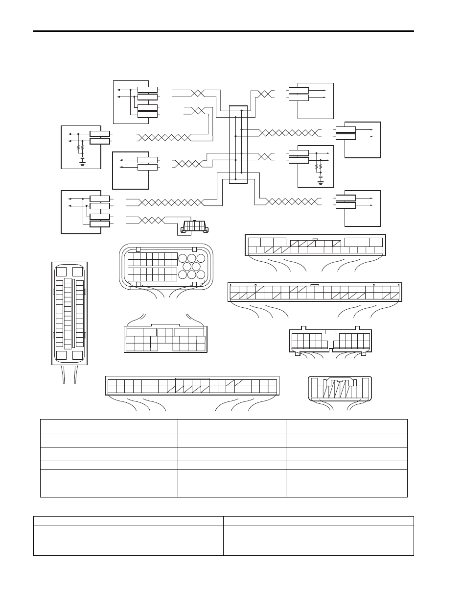
Wiring Diagram
DTC Detecting Condition and Trouble Area
WHT
RED
WHT
RED
WHT/BLU
WHT
RED
WHT
RED
E91-22
E91-23
E53-13
E53-44
E53-46
WHT/BLU
WHT/RED
E23-17
E23-9
G31-1
G31-3
G44-19
G44-18
WHT
RED
WHT
RED
E92-17
E92-7
[F]
G44
1
2
3
4
5
6
7
8
9
10
11
14
15
16
36
34 33 32 31 30 29
24 23
37
18
19
20
[C]
6
5
16 15 14 13 12 11
4 3
24 23
21
22
10 9
8
7
2
1
19
20
18 17
E92
[G]
1
2
3
4
5
6
7
8
9
10
11
17
1615141312
2221201918
G28
[D]
G31
1
2
3
4
7
8
9
10
11
14
15
16
36
34
35
24 23
21
22
28 27
25
26
37
39 38
40
18 17
13 12
19
20
E91
1
2
3
10
11
12
16
17
18
15 14 13
19
20
21
25
26
5
6
[E]
G28-8
G28-10
G45-9
G45-10
WHT/RED
E53-42
WHT
RED
WHT
RED
[B]
17
18
19
20
21
22
23
24
25
26
27
28
29
30
31
33
34
35
36
37
38
39
40
32
1
2
3
4
5
6
7
8
9
10
11
12
13
14
15
16
E23
[A]
E53
16
1
15
2
3
4
5
6
7
8
9
10
11
12
13
14
17
18
19
20
21
22
23
24
25
26
27
28
29
30
31
32
33
34
35
36
37
38
39
40
41
42
43
44
45
46
47
[H]
G45
10 9
3 2 1
1
2
3
4
9
5
7
6
8
G31-2
G31-4
10
I6JB01460023-02
[A]: ESP
® control module connector (viewed from
terminal side)
[G]: Combination meter connector (viewed
from harness side)
5. 4WD control module (if equipped)
[B]: ECM connector (viewed from harness side)
[H]: Steering angle sensor connector
(viewed from harness side)
6. Keyless start control module (if equipped)
[C]: TCM connector (viewed from harness side)
1. ESP
® hydraulic unit / control module
assembly
7. Combination meter
[D]: BCM connector (viewed from harness side)
2. ECM
8. Steering angle sensor (if equipped)
[E]: 4WD control module connector (viewed from
harness side)
3. TCM
9. Junction connector
[F]: Keyless start control module connector (viewed
from harness side)
4. BCM
10. Data link connector (DLC)
DTC Detecting Condition
Trouble Area
TCM message data is missing from CAN communication.
(A/T model)
• CAN communication circuit
• TCM
• ESP
® control module

Electronic Stability Program: 4F-38
DTC Troubleshooting
Step
Action
Yes
No
1
Was “Electronic Stability Program Check” performed?
Go to Step 2.
Go to “Electronic
Stability Program
Check”.
2
DTC check for ESP
®
1) Check DTC for ESP
®.
Is DTC U1101 and DTC U1073 detected together?
Go to “DTC U1073:
Control Module
Communication Bus Off
in Section 4E” for
troubleshooting.
Go to Step 3.
3
DTC check for TCM
1) Check DTC for TCM.
Is DTC U0073 detected?
Go to “DTC U0073:
Control Module
Communication Bus Off
in Section 5A” for
troubleshooting.
Go to Step 4.
4
Check each control module connectors
1) Check connection of connectors of all control modules
communicating by means of CAN.
2) Check DTC for ESP
®.
Is DTC U1101 detected?
Go to Step 5.
Check for intermittent
trouble referring to
“Intermittent and Poor
Connection Inspection
in Section 00”.
5
CAN communication circuit check
1) Turn ignition switch to OFF position.
2) Disconnect connectors of ESP
® control module, TCM
and BCM communicating by means of CAN.
Is each CAN communication circuit between ESP
®
control
module, TCM and BCM opened, shorted or high resistance?
Repair or replace the
CAN communication
line.
Go to Step 6.
6
DTC check for ESP
®
1) Turn ignition switch to OFF position.
2) Disconnect connectors of all control modules
communicating by means of CAN.
3) Connect connectors to ESP
® control module and TCM.
4) Check DTC for ESP
®.
Is DTC U1101 detected?
Go to Step 7.
Go to Step 8.
7
DTC Check for BCM
1) Turn ignition switch to OFF position.
2) Connect connector to BCM.
3) Check DTC for BCM.
Is DTC U1101 detected?
Check TCM power and
ground circuit. If circuit
is OK, substitute a
known-good TCM and
check DTC.
Check ESP
® power
and ground circuit. If
circuit is OK, substitute
a known-good ESP
®
hydraulic unit / control
module assembly and
check DTC.
8
CAN communication circuit check
1) Turn ignition switch to OFF position.
Is each CAN communication circuit between disconnected
control modules (other than ESP
®
control module and TCM)
opened, shorted or high resistance?
Repair or replace the
CAN communication
line.
Go to Step 9.
Нет комментариевНе стесняйтесь поделиться с нами вашим ценным мнением.
Текст