Suzuki Grand Vitara JB627. Service manual — part 45
1A-129 Engine General Information and Diagnosis:
DTC P0444 / P0445: EVAP Emission System Purge Control Valve Circuit Open / Shorted
S6JB0B1104046
Wiring Diagram
DTC Detecting Condition and Trouble Area
DTC Confirmation Procedure
WARNING
!
• When performing a road test, select a place where there is no traffic or possibility of a traffic
accident and be very careful during testing to avoid occurrence of an accident.
• Road test should be carried out with 2 persons, a driver and a tester, on a level road.
1) With ignition switch turned OFF, connect scan tool.
2) Turn ON ignition switch and clear DTC by using scan tool if any.
3) Start engine and warm it up to normal operating temperature.
4) Drive vehicle in 4000 r/min. or less of engine speed for 10 seconds or longer.
5) Stop vehicle and check DTC by using scan tool.
BLU/BLK
BLU/BLK
BLU/BLK
BLK/RED
BLK/RED
BLK/RED
BLU
12V 5V
E23-8
E23-16
E23-2
E23-3
WHT/GRN
C37-59
C37-58
C37-39
C37-73
C37-80
BLK/YEL
BLK/ORN
BLK/ORN
BLK/YEL
BLK/YEL
1
3 2
4
5
6
7
8
9
1110
12
13
14
15
16
17
18
19
20
17
18
19
20
21
22
23
24
25
26
27
28
29
30
31
33
34
35
36
37
38
39
40
32
1
2
3
4
5
6
7
8
9
10
11
12
13
14
15
16
21
22
23
24
25
26
27
28
29
30
31
32
33
34
35
36
37
38
39
40
41
42
43
44
45
46
47
48
49
50
51
52
53
54
55
56
57
58
59
60
61
62
63
64
65
66
67
68
69
70
71
72
73
74
75
76
77
78
79
80
81
E23
C37
BLK/ORN
C37-81
BLK/YEL
BLK/WHT
C37-10
GRN/BLK
7
8
4
5
3
2
P
1
C
6
I6JB01110040-03
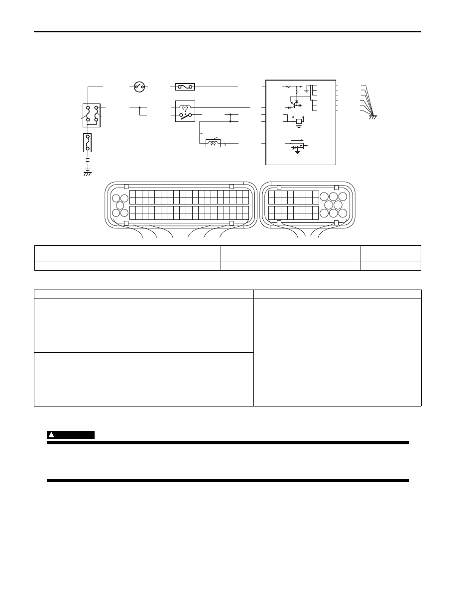
P: EVAP canister purge valve power supply circuit
2. Main relay
5. Ignition switch
8. “IGN” fuse
C: EVAP canister purge valve control circuit
3. “IG COIL” fuse
6. ECM
1. EVAP canister purge valve
4. Fuse box No.2
7. “FI” fuse
DTC detecting condition
Trouble area
DTC P0444: EVAP Emission System Purge Control Valve
Circuit Open
EVAP canister purge valve control duty (on 48% ON duty or less)
is continuous 240 pulses or more and purge valve circuit voltage is
3.0 V or less during OFF duty pulse condition.
(1 driving cycle detection logic)
• EVAP canister purge valve and its circuit
• ECM
DTC P0445: EVAP Emission System Purge Control Valve
Circuit Shorted
EVAP canister purge valve control duty (on 50% ON duty or less)
is continuous 240 pulses or more and purge valve circuit voltage is
8.4 V or more during OFF duty pulse condition.
(1 driving cycle detection logic)

Engine General Information and Diagnosis: 1A-130
DTC Troubleshooting
NOTE
Before this trouble shooting is performed, read the precautions for DTC troubleshooting referring to
“Precautions for DTC Troubleshooting”.
Step
Action
Yes
No
1
Was “Engine and Emission Control System Check”
performed?
Go to Step 2.
Go to “Engine and
Emission Control
System Check”.
2
EVAP canister purge valve power supply voltage check
1) Disconnect connector from EVAP canister purge valve
with ignition switch turned OFF.
2) Check for proper terminal connection to EVAP canister
purge valve and ECM connectors.
3) If connections are OK, check that EVAP canister purge
valve power supply voltage is battery voltage between
EVAP canister purge valve connector and vehicle body
ground with ignition switch turned ON.
Is it in good condition?
Go to Step 3.
Repair or replace EVAP
canister purge valve
power supply circuit.
3
Wire harness check
1) Disconnect connector from ECM with ignition switch
turned OFF.
2) Check that EVAP canister purge valve circuit is as
follows.
• Wiring harness resistance of EVAP canister purge
valve control circuit is less than 3
Ω.
• Insulation resistance of EVAP canister purge valve
control circuit is infinity between EVAP canister purge
valve connector and vehicle body ground.
• Circuit voltage of EVAP canister purge valve control
circuit is 0 – 1 V with ignition switch turned ON.
Are they in good condition?
Go to Step 4.
Repair or replace
defective wire harness.
4
EVAP canister purge valve check
1) Check EVAP canister purge valve coil resistance
referring to “EVAP Canister Purge Valve Inspection in
Section 1B”.
Is it in good condition?
Substitute a known
good ECM and recheck.
Replace EVAP canister
purge valve.
1A-131 Engine General Information and Diagnosis:
DTC P0462 / P0463: Fuel Level Sensor Circuit Low / High
S6JB0B1104047
Wiring Diagram
DTC Detecting Condition and Trouble Area
DTC Confirmation Procedure
1) With ignition switch OFF, connect scan tool.
2) Turn ON ignition switch and clear DTC by using scan tool if any.
3) Start engine and run it for 10 sec.
4) Check DTC and pending DTC by using scan tool.
1
3 2
4
5
6
7
8
9
1110
12
13
14
15
16
17
18
19
20
17
18
19
20
21
22
23
24
25
26
27
28
29
30
31
33
34
35
36
37
38
39
40
32
1
2
3
4
5
6
7
8
9
10
11
12
13
14
15
16
21
22
23
24
25
26
27
28
29
30
31
32
33
34
35
36
37
38
39
40
41
42
43
44
45
46
47
48
49
50
51
52
53
54
55
56
57
58
59
60
61
62
63
64
65
66
67
68
69
70
71
72
73
74
75
76
77
78
79
80
81
E23
C37
12 V
E23-28
YEL/RED
BLK/YEL
YEL/GRN
BLU/BLK
WHT/GRN
BLU/BLK
BLU/BLK
BLK/RED
BLK/RED
BLK/RED
BLU
12V 5V
E23-8
E23-24
E23-16
E23-2
E23-3
WHT/GRN
C37-59
C37-58
C37-39
C37-73
C37-80
BLK/YEL
BLK/ORN
BLK/ORN
BLK/YEL
BLK/YEL
BLK/ORN
C37-81
BLK/YEL
BLK/WHT
BLK/WHT
BLK/WHT
BLK
PNK
5
6
7
1
2
3
4
I6JB01110060-03
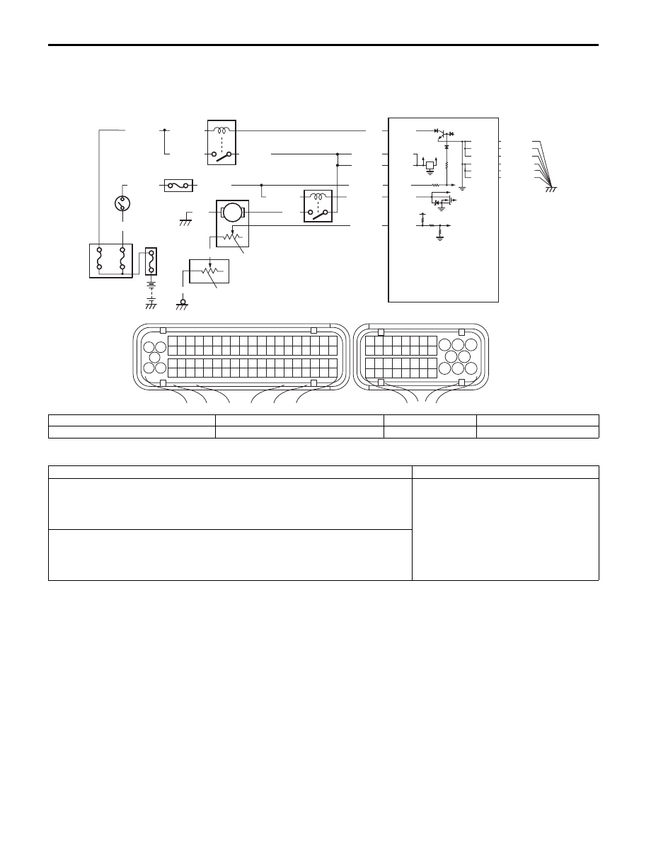
1. Fuel pump assembly
3. Main fuel level sensor
5. ECM
7. Fuel pump relay
2. Fuel pump
4. Sub fuel level sensor
6. Main relay
DTC detecting condition
Trouble area
DTC P0462: Fuel Level Sensor Circuit Low Input
Circuit voltage of fuel level sensor is less than voltage specification calculated
from battery voltage.
(2 driving cycle detection logic)
• Fuel level sensor and/or its circuit
• ECM
DTC P0463: Fuel Level Sensor Circuit High Input
Circuit voltage of fuel level sensor is more than voltage specification
calculated from battery voltage.
(2 driving cycle detection logic)

Engine General Information and Diagnosis: 1A-132
DTC Troubleshooting
Step
Action
Yes
No
1
Was “Engine and Emission Control System Check”
performed?
Go to Step 2.
Go to “Engine and
Emission Control
System Check”.
2
Fuel level sensor performance check
1) Check fuel level sensor (main and sub) for performance
referring to “Fuel Level Sensor Inspection in Section
9C”.
Is it in good condition?
Go to Step 3.
Replace main and/or
sub fuel level sensor.
3
Wire harness check
1) Disconnect connectors from ECM with ignition switch
turned OFF.
2) Check for proper terminal connection to fuel level sensor
(main and sub) and ECM connectors.
3) If connections are OK, check that fuel level sensor circuit
is as follows.
• Wiring harness resistance of fuel level sensor (main
and sub) circuit is less than 3
Ω.
• Insulation resistance of fuel level sensor (main and
sub) circuit is infinity between fuel level sensor (main
and sub) connector and vehicle body ground.
• Insulation resistance of wire harness is infinity
between fuel level sensor (main and sub) terminal and
each other terminal at fuel level sensor connector.
• Circuit voltage of fuel level sensor (main and sub)
circuit is 0 – 1 V with ignition switch turned ON.
Are they in good condition?
Substitute a known
good ECM and recheck.
Repair or replace
defective wire harness.
Нет комментариевНе стесняйтесь поделиться с нами вашим ценным мнением.
Текст