Suzuki Grand Vitara JB627. Service manual — part 46
1A-133 Engine General Information and Diagnosis:
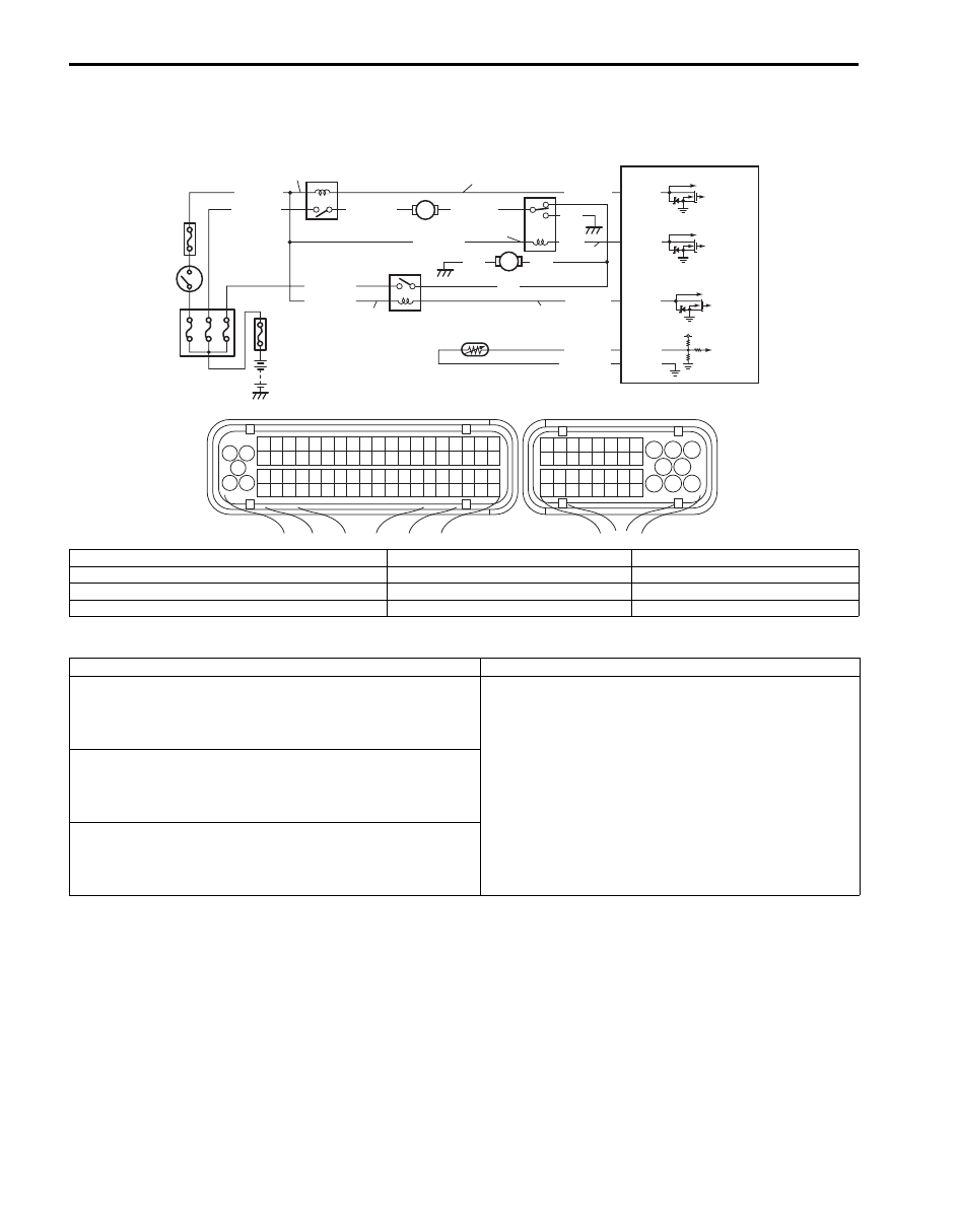
DTC P0480 / P0481 / P0482: Fan 1 / Fan 2 / Fan 3 Control Circuit
S6JB0B1104048
Wiring Diagram
DTC Detecting Condition and Trouble Area
DTC Confirmation Procedure
1) With ignition switch turned OFF, connect scan tool.
2) Turn ON ignition switch and clear DTC by using scan tool if any.
3) Start engine and warm up to normal operating temperature.
4) Keep engine at idle speed until engine coolant temperature reaches 102
°C (216 °F) or more.
5) Check DTC by using scan tool.
1
3 2
4
5
6
7
8
9
1110
12
13
14
15
16
17
18
19
20
17
18
19
20
21
22
23
24
25
26
27
28
29
30
31
33
34
35
36
37
38
39
40
32
1
2
3
4
5
6
7
8
9
10
11
12
13
14
15
16
21
22
23
24
25
26
27
28
29
30
31
32
33
34
35
36
37
38
39
40
41
42
43
44
45
46
47
48
49
50
51
52
53
54
55
56
57
58
59
60
61
62
63
64
65
66
67
68
69
70
71
72
73
74
75
76
77
78
79
80
81
E23
C37
BLU/BLK
BLK
RED
YEL/GRN
RED/YEL
BLK
BLU
BLU
BLU/WHT
YEL/GRN
E23-37
E23-15
E23-23
E23-14
YEL/GRN
BLU/RED
BLU/YEL
RED/BLK
5V
C37-26
C37-67
PPL/YEL
GRY/GRN
6
4
P
7
C
C
5
P
9
8
10
2
1
P
3
C
I6JB01110042-03
P: Radiator cooling fan relay power supply circuit
3. Radiator cooling fan relay No.1
7. Radiator cooling fan motor No.2
C: Radiator cooling fan relay control circuit
4. Radiator cooling fan relay No.2
8. ECM
1. Fuse Box No.2
5. Radiator cooling fan relay No.3
9. ECT sensor
2. Ignition switch
6. Radiator cooling fan motor No.1
10. “IG2 SIG” fuse
DTC detecting condition
Trouble area
DTC P0480: Fan 1 Control Circuit
No.1 radiator cooling fan relay circuit voltage is more than
8.4 V at relay ON or less than 3.0 V at relay OFF.
(1 driving cycle detection logic)
• Radiator cooling fan relay No.1 and its circuit (P0480)
• Radiator cooling fan relay No.2 and its circuit (P0481)
• Radiator cooling fan relay No.3 and its circuit (P0482)
• ECM
DTC P0481: Fan 2 Control Circuit
No.2 radiator cooling fan relay circuit voltage is more than
8.4 V at relay ON or less than 3.0 V at relay OFF.
(1 driving cycle detection logic)
DTC P0482: Fan 3 Control Circuit
No.3 radiator cooling fan relay circuit voltage is more than
8.4 V at relay ON or less than 3.0 V at relay OFF.
(1 driving cycle detection logic)

Engine General Information and Diagnosis: 1A-134
DTC Troubleshooting
NOTE
Before this trouble shooting is performed, read the precautions for DTC troubleshooting referring to
“Precautions for DTC Troubleshooting”.
Step
Action
Yes
No
1
Was “Engine and Emission Control System Check”
performed?
Go to Step 2.
Go to “Engine and
Emission Control
System Check”.
2
Wire harness check
1) Turn ignition switch to OFF position.
2) Check for proper terminal connection to related radiator
cooling fan relay (No.1, No.2 or No.3) and ECM
connectors.
3) If connections are OK, recheck DTC.
Is DTC P0480, P0481 or P0482 detected again?
Go to Step 3.
Intermittent trouble.
3
Radiator cooling fan control circuit voltage check
1) Turn ignition switch to OFF position.
2) Disconnect connectors from ECM.
3) Turn ignition switch ON position.
4) Check that related radiator cooling fan relay (No.1, No.2
or No.3) control circuit voltage is battery voltage between
ECM connector and vehicle body ground.
Is it in good condition?
Go to Step 4.
Substitute a known
good ECM and recheck.
4
Radiator cooling fan control circuit voltage check
1) Turn ignition switch to OFF position.
2) Remove radiator cooling fan relay No.1, No.2 or No.3.
3) Turn ignition switch ON position.
4) Check that related radiator cooling fan relay (No.1, No.2
or No.3) power supply voltage is battery voltage between
radiator cooling fan relay (No.1, No.2 or No.3) connector
and vehicle body ground.
Is it in good condition?
Go to Step 5.
Repair or replace power
supply circuit of radiator
cooling fan relay (No.1,
No.2 or No.3).
5
Radiator cooling fan relay check
1) Check radiator cooling fan relay No.1, No.2 or No.3 for
operation referring to “Radiator Cooling Fan Relay
Inspection in Section 1F”.
Is it in good condition?
Repair or replace
control circuit of radiator
cooling fan relay (No.1,
No.2 or No.3). If circuit
is OK, substitute a
known good ECM and
recheck.
Replace radiator cooling
fan relay No.1, No.2 or
No.3.
1A-135 Engine General Information and Diagnosis:
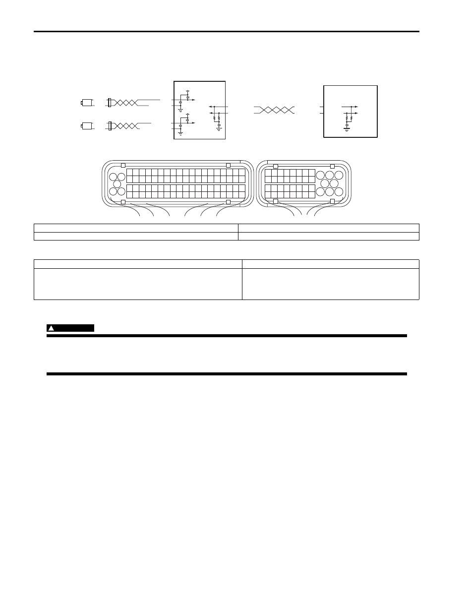
DTC P0500: Vehicle Speed Sensor
S6JB0B1104049
Wiring Diagram
DTC Detecting Condition and Trouble Area
DTC Confirmation Procedure
WARNING
!
• When performing a road test, select a place where there is no traffic or possibility of a traffic
accident and very careful during testing to avoid occurrence of an accident.
• Road test should be carried out with 2 persons, a driver and a tester, on a level road by ECM.
1) With ignition switch OFF, connect scan tool.
2) Turn ON ignition switch and clear DTC by using scan tool if any.
3) Start engine and warm up to normal operating temperature.
4) Increase vehicle speed till engine speed is reached 4000 rpm in 3rd gear (M/T) or 2nd range (A/T).
5) Release accelerator pedal and with engine brake applied, keep vehicle coasting and then stop vehicle.
6) Check DTC by using scan tool.
1
3 2
4
5
6
7
8
9
1110
12
13
14
15
16
17
18
19
20
17
18
19
20
21
22
23
24
25
26
27
28
29
30
31
33
34
35
36
37
38
39
40
32
1
2
3
4
5
6
7
8
9
10
11
12
13
14
15
16
21
22
23
24
25
26
27
28
29
30
31
32
33
34
35
36
37
38
39
40
41
42
43
44
45
46
47
48
49
50
51
52
53
54
55
56
57
58
59
60
61
62
63
64
65
66
67
68
69
70
71
72
73
74
75
76
77
78
79
80
81
E23
C37
E23-9
WHT/RED
WHT/BLU
WHT/RED
WHT/BLU
BLK
WHT
BLK
WHT
YEL/BLK
YEL
LT GRN
LT GRN/BLK
12V
12V
E23-17
1
2
3
4
I5JB0C110012-01
1. Rear left side wheel speed sensor (VSS 1)
3. ABS or ESP
® control module Assembly
2. Rear right side wheel speed sensor (VSS 2)
4. ECM
DTC detecting condition
Trouble area
Wheel speed signal (RL and/or RR) is 0.6 mph or less even
though signal sent from CAN is 4000 rpm or less with fuel cut.
(1 driving cycle detection logic)
• Wheel speed sensor (RR and/or RL) and its circuit
• Wheel speed encoder (RR and/or RL)
• ABS or ESP
® control module
Engine General Information and Diagnosis: 1A-136
DTC Troubleshooting
NOTE
• Before this trouble shooting is performed, read the precautions for DTC troubleshooting referring to
“Precautions for DTC Troubleshooting”.
• Make sure that DTC of CAN communication is not detected by ECM.
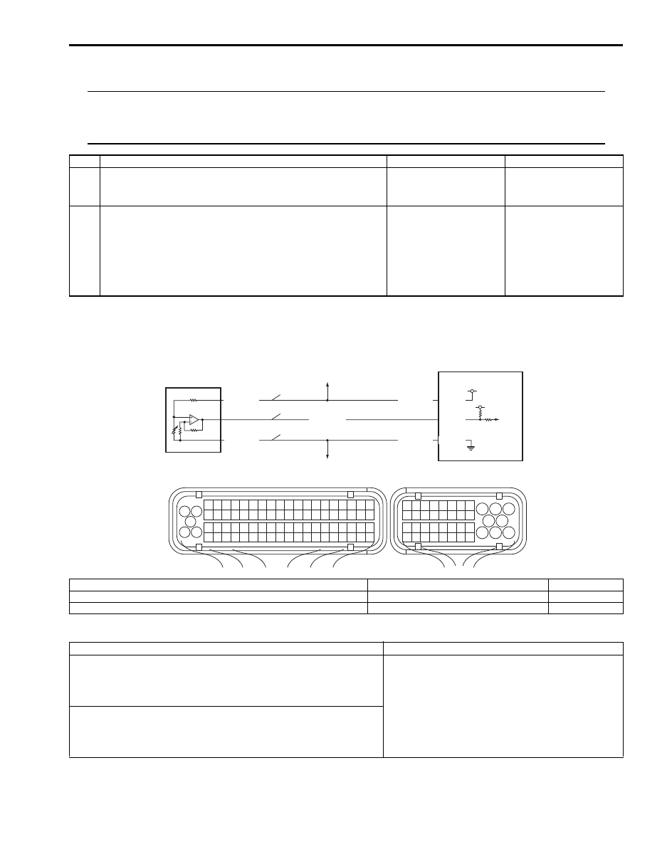
DTC P0532 / P0533: A/C Refrigerant Pressure Sensor Circuit Low / High
S6JB0B1104050
Wiring Diagram
DTC Detecting Condition and Trouble Area
Step
Action
Yes
No
1
Was “Engine and Emission Control System Check”
performed?
Go to Step 2.
Go to “Engine and
Emission Control
System Check”.
2
DTC check in ABS control module
1) Connect scan tool to DLC with ignition switch turned
OFF.
2) Check DTC in ABS or ESP
® control module.
Is there DTC(s) of rear wheel speed sensor detected?
Go to applicable DTC
diag. Flow.
Check for intermittent
referring to “Intermittent
and Poor Connection
Inspection in Section
00”. If OK, substitute a
known good ECM and
recheck.
1
3 2
4
5
6
7
8
9
1110
12
13
14
15
16
17
18
19
20
17
18
19
20
21
22
23
24
25
26
27
28
29
30
31
33
34
35
36
37
38
39
40
32
1
2
3
4
5
6
7
8
9
10
11
12
13
14
15
16
21
22
23
24
25
26
27
28
29
30
31
32
33
34
35
36
37
38
39
40
41
42
43
44
45
46
47
48
49
50
51
52
53
54
55
56
57
58
59
60
61
62
63
64
65
66
67
68
69
70
71
72
73
74
75
76
77
78
79
80
81
E23
C37
4
1
2
3
GRY/RED
5V
5V
C37-49
C37-48
GRY/BLK
GRY/GRN
GRY/RED
GRY/GRN
C37-67
P
S
G
I6JB01110045-03
P: A/C refrigerant pressure sensor power supply circuit
1. A/C refrigerant pressure sensor
4. ECM
S: A/C refrigerant pressure sensor signal circuit
2. To other sensors
G: A/C refrigerant pressure sensor ground circuit
3. To other sensors
DTC detecting condition
Trouble area
DTC P0532: A/C Refrigerant Pressure Sensor Circuit Low
Output voltage of A/C refrigerant pressure sensor is less than 0.15
V for 5 seconds or longer.
(1 driving cycle detection logic but MIL does not light up)
• A/C refrigerant pressure sensor and its circuit
• ECM
DTC P0533: A/C Refrigerant Pressure Sensor Circuit High
Output voltage of A/C refrigerant pressure sensor is more than
4.95 V for 5 seconds or longer.
(1 driving cycle detection logic but MIL does not light up)
Нет комментариевНе стесняйтесь поделиться с нами вашим ценным мнением.
Текст