Suzuki Grand Vitara JB627. Service manual — part 435
10E-25 Keyless Start System:
Keyless Start Control Module Power and Ground Circuit Check
S6JB0BA504016
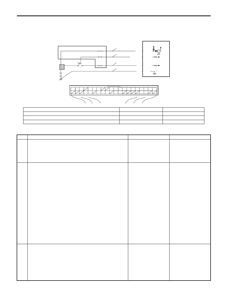
Wiring Diagram
Troubleshooting
BLK G44-9
G44-15
G44-10
G44-11
WHT/BLK
WHT
YEL
5V
12V
G44
[A]
1
2
3
4
5
6
7
8
9
10
11
14
15
16
36
34 33 32
30 29
24 23
37
18
19
20
5
2
4
1
3
3
3
6
7
8
9
I7JB01A50003-01
[A]: Keyless start control module connector (viewed from harness side)
4. Main fuse
8. IG ON signal circuit
1. Keyless start control module
5. Junction block
9. Ground circuit
2. Ignition switch
6. Power source circuit
3. Circuit fuse
7. ACC signal circuit
Step
Action
Yes
No
1
Fuse check
1) Turn ignition switch to OFF position.
2) Check circuit fuse and main fuse for condition.
Are fuses in good condition?
Go to Step 2.
Replace fuse(s) and
check for short.
2
Power supply circuit check
1) Disconnect connector from keyless start control module.
2) Check for proper connection to “Power source”, “ACC
signal” and “IG ON signal” terminal of keyless start
control module connector.
3) If OK, measure voltage between following terminals.
• “Power source” terminal of keyless start control
module connector and vehicle body ground with
ignition switch is at OFF position
• “ACC signal” terminal of keyless start control module
connector and vehicle body ground with ignition
switch is at ACC position
• “IG ON signal” terminal of keyless start control module
connector and vehicle body ground with ignition
switch is at ON position
Is each terminal voltage is 10 – 14 V?
Go to Step 3.
Repair defective power
supply circuit.
3
Ground circuit check
1) Check for proper connection to “Ground” terminal of
keyless start control module connector.
2) If OK, measure resistance between “Ground” terminal of
keyless start control module connector and vehicle body
ground.
Is resistance 1
Ω
or less?
Power and ground
circuit is in good
condition.
Repair ground circuit.
Keyless Start System: 10E-26
DTC No. 11: Communication Error with Steering Lock Unit
S6JB0BA504017
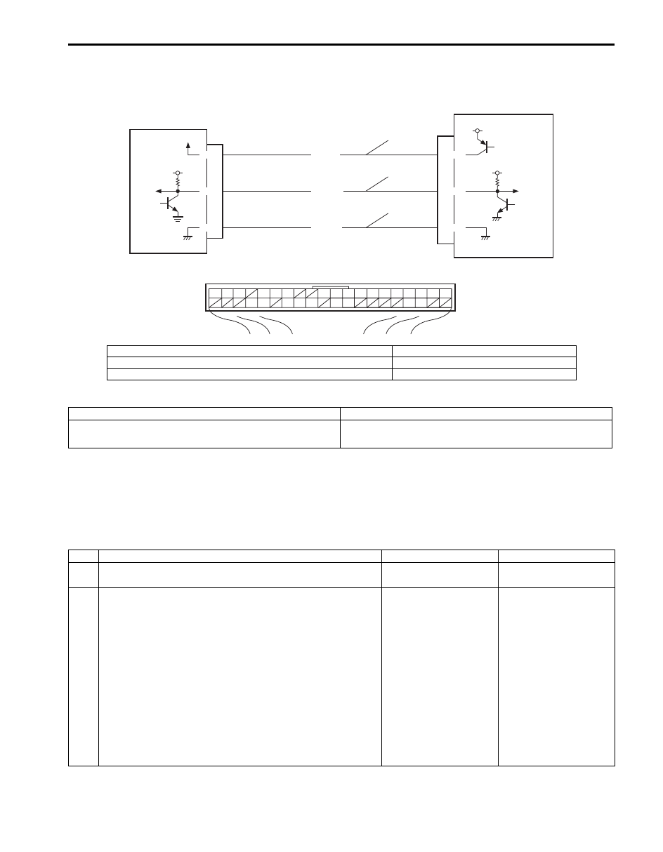
Wiring Diagram
DTC Detecting Condition and Trouble Area
DTC Confirmation Procedure
1) Clear DTC referring to “DTC Clearance”.
2) Turn ignition knob switch pushing ignition knob switch.
3) Check DTC referring to “DTC Check”.
Troubleshooting
G44
[A]
1
2
3
4
5
6
7
8
9
10
11
14
15
16
36
34 33 32
30 29
24 23
37
18
19
20
5V
G44-20
G44-29
G44-30
G22-3
G22-7
G22-8
5V
5V
ORN
BRN/YEL
BLK/YEL
5V
2
1
3
4
5
I7JB01A50004-01
[A]: Keyless start control module connector (viewed from harness side)
3. Steering lock unit power supply circuit
1. Keyless start control module
4. Steering lock unit signal circuit
2. Steering lock unit
5. Steering lock unit ground circuit
DTC detecting condition
Trouble area
No communication is available between keyless start
control module and steering lock unit.
• Steering lock unit and its circuit
• Keyless start control module
Step
Action
Yes
No
1
Was “Keyless Start System Check” performed?
Go to Step 2.
Go to “Keyless Start
System Check”.
2
Steering lock unit circuit check
1) Disconnect connector from keyless start control module.
2) Check for proper connection to “Steering lock unit power
supply”, “Steering lock unit signal” and “Steering lock unit
ground” terminals of keyless start control module
connector.
3) If OK, check for open, short and high resistance in
following circuits.
• Steering lock unit power supply circuit
• Steering lock unit signal circuit
• Steering lock unit ground circuit
Is each circuit in good condition?
Go to Step 3.
Repair circuit.

10E-27 Keyless Start System:
DTC No. 13 / No. 14: Release Signal Error from Steering Lock Unit / Steering Lock Unit Malfunction
S6JB0BA504018
DTC Detecting Condition and Trouble Area
DTC Confirmation Procedure
1) Clear DTC referring to “DTC Clearance”.
2) Turn ignition knob switch pushing ignition knob switch.
3) Check DTC referring to “DTC Check”.
Troubleshooting
Replace steering lock unit and recheck.
NOTE
Be sure to register the following code when a used keyless start control module is installed. Otherwise
DTC No.13 is detected by keyless start control module though steering lock unit is normal.
• With immobilizer control system, ignition key transponder code is not registered in ECM.
• Without immobilizer control system, steering lock unit ID code is not registered in keyless start
control module.
DTC No. 21 / No. 22: Internal Error of Keyless Start Control Module (EEPROM Reading Error) /
(EEPROM Writing Error)
S6JB0BA504019
DTC Detecting Condition and Trouble Area
DTC Confirmation Procedure
1) Clear DTC referring to “DTC Clearance”.
2) Turn ignition knob switch pushing ignition knob switch.
3) Push request switch of each door.
4) Check DTC referring to “DTC Check”.
Troubleshooting
Substitute a known-good keyless start control module and recheck.
3
Steering lock unit power supply voltage check
1) Connect connector to keyless start control module.
2) Measure voltage between “Steering lock unit power
supply” terminal of steering lock unit connector and
vehicle body ground.
Is voltage 4 – 6 V?
Replace steering lock
unit.
Substitute a known-
good keyless start
control module and
recheck.
Step
Action
Yes
No
DTC detecting condition
Trouble area
DTC No. 13:
Although lock release signal is output to steering lock unit, no lock
release signal is inputted from steering lock unit.
(wire harness is normal)
DTC No. 14:
Although lock release signal is output to steering lock unit,
steering lock is not released due to temperature rise of steering
lock unit solenoid and no lock release signal is inputted.
(wire harness is normal)
• Steering lock unit
DTC detecting condition
Trouble area
DTC No. 21:
Data cannot be read from memory in keyless start control module.
DTC No. 22:
Data cannot be written into memory in keyless start control
module.
• Keyless start control module
Keyless Start System: 10E-28
DTC No. 31: Lost Communication with BCM
S6JB0BA504020
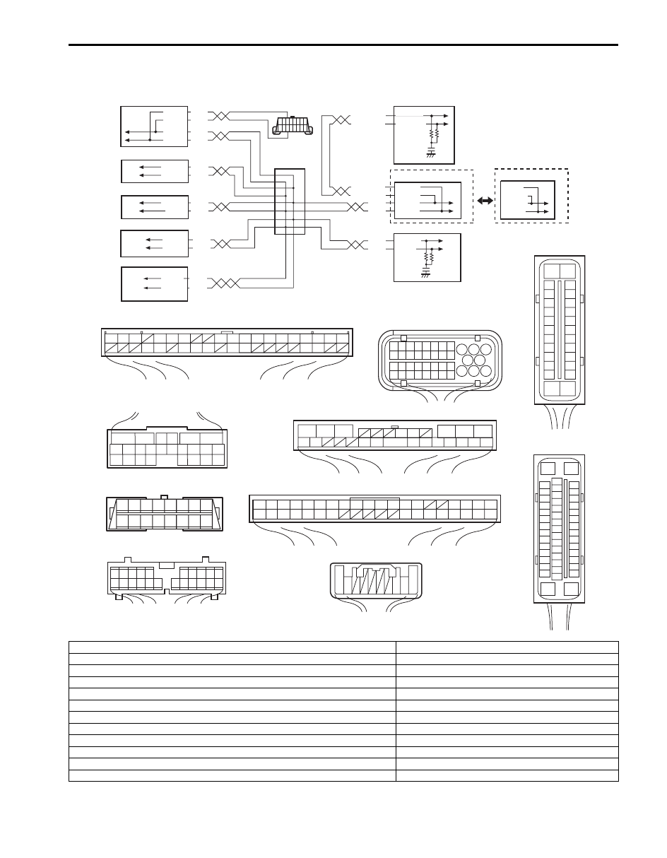
Wiring Diagram
WHT
RED
WHT
RED
G44-18
G44-19
G44
[A]
[C]
[H]
[G]
1
2
3
4
5
6
7
8
9
10
11
14
15
16
36
34 33 32
30 29
24 23
37
18
19
20
G28-8
G28-10
WHT/BLU
WHT/BLU
WHT/RED
WHT/RED
E23-9
E23-17
WHT
RED
E53-13
E53-42
E53-44
E53-46
WHT
RED
E92-17
E92-7
WHT
RED
E91-22
E91-23
WHT
RED
RED
G31-1
G31-3
G31-4
6
5
16 15 14 13 12 11
4 3
24 23
21
22
10 9
8
7
2
1
19
20
18 17
E92
1
2
3
4
5
6
7
8
9
10
11
17
1615141312
2221201918
G28
[F]
G31
E91
1
2
3
4
7
8
9
10
11
14
15
16
36
34
35
24 23
21
22
28 27
25
26
37
39 38
40
18 17
13 12
19
20
1
2
3
10
11
12
16
17
18
15 14 13
19
20
21
25
26
5
6
[E]
[D]
E03
15
16
17
18
19
20
21
22
23
24
25
2
3
4
5
6
7
8
9
10
11
12
1
13
14
26
8 7 6 5 4 3 2 1
9
10
11
12
13
14
15
16
G31-2
WHT
1
2
3
4
9
5
6
7
8
11
WHT
RED
G45-9
G45-10
10
[L]
[K]
E03-12
E03-10
E03-6
E03-8
[I]
E53
16
1
15
2
3
4
5
6
7
8
9
10
11
12
13
14
17
18
19
20
21
22
23
24
25
26
27
28
29
30
31
32
33
34
35
36
37
38
39
40
41
42
43
44
45
46
47
[J]
G45
10 9
3 2 1
[B]
E23
17
18
19
20
21
22
23
24
25
26
27
28
29
30
31
33
34
35
36
37
38
39
40
32
1
2
3
4
5
6
7
8
9
10
11
12
13
14
15
16
I6JB0BA50002-01
[A]: Keyless start control module connector (viewed from harness side)
1. BCM
[B]: ECM connector (viewed from harness side)
2. 4WD control module (if equipped)
[C]: TCM connector (viewed from harness side)
3. TCM (A/T model)
[D]: DLC (viewed from terminal side)
4. Keyless start control module
[E]: ABS control module connector (viewed from terminal side)
5. DLC
[F]: Combination meter connector (viewed from harness side)
6. ECM
[G]: 4WD control module connector (viewed from harness side)
7. ABS control module
[H]: BCM connector (viewed from harness side)
8. Combination meter
[I]: ESP
® control module connector (viewed from terminal side)
9. Junction connector
[J]: Steering angle sensor connector (viewed from harness side)
10. ESP
® control module
[K]: ESP
® model
11. Steering angle sensor (if equipped)
[L]: Other than ESP
® model
Нет комментариевНе стесняйтесь поделиться с нами вашим ценным мнением.
Текст