Suzuki Grand Vitara JB627. Service manual — part 433

10E-17 Keyless Start System:
G44-7
Luggage room antenna (–)
*–10 – 10 V
Refer to “Reference waveform No. 3: ”
G44-8
Luggage room antenna (+)
*–8 – 14 V
G44-9
Ground for keyless start control module
0 – 1 V
Ignition switch is at all positions
G44-10
Power source
10 – 12 V
Ignition switch is at all positions
G44-11
Ignition switch (ACC signal)
10 – 12 V
Ignition switch is at ACC or ON position
0 – 1 V
Ignition switch is at any position other than
ACC or ON position
G44-12
—
—
—
G44-13
—
—
—
G44-14
Ignition switch (key reminder signal)
10 – 12 V
Insert ignition key to ignition key cylinder
0 – 1 V
Pull out ignition key from ignition key
cylinder
G44-15
Ignition switch (ON signal)
10 – 12 V
Ignition switch is at ON position
0 – 1 V
Ignition switch is at any position other than
ON position
G44-16
Driver side door request switch
10 – 12 V
Request switch of driver side door is
released
0 – 1 V
Request switch of driver side door is
pushed
G44-17
—
—
—
G44-18
CAN communication line (low)
*1.6 – 2.5 V
Refer to “Reference waveform No. 4: ”
G44-19
CAN communication line (high)
*2.5 – 3.6 V
G44-20
Power supply for steering lock unit
4 – 6 V
Full time
G44-21
—
—
—
G44-22
—
—
—
G44-23
Passenger side door antenna (–)
*0 – 5 V
Refer to “Reference waveform No. 1: ”
G44-24
Passenger side door antenna (+)
G44-25
—
—
—
G44-26
—
—
—
G44-27
—
—
—
G44-28
—
—
—
G44-29
Signal for steering lock unit
4 – 6 V
Ignition knob switch is at any position other
than ON and OFF position
*0 – 5 V
Refer to “Reference waveform No. 5: ”
G44-30
Ground for steering lock unit
0 – 1 V
Full time
G44-31
—
—
—
G44-32
Rear end door request switch
10 – 12 V
Request switch of rear end door is at any
position other than ON position
0 – 1 V
Request switch of rear end door is at ON
position
G44-33
Driver side door lock switch
*0 – 5 V
Refer to “Reference waveform No. 6: ”
G44-34
Ignition knob switch
10 – 12 V
When pushing ignition knob switch of
steering lock unit
0 – 1 V
When releasing ignition knob switch of
steering lock unit
G44-35
—
—
—
G44-36
Passenger side door request switch
10 – 12 V
Request switch of passenger side door is
at any position other than ON position
0 – 1 V
Request switch of passenger side door is
at ON position
G44-37
Passenger side door lock switch
*0 – 5 V
Refer to “Reference waveform No. 6: ”
G44-38
—
—
—
G44-39
—
—
—
G44-40
—
—
—
Terminal
Number
Circuit
Normal
Voltage
Condition
Keyless Start System: 10E-18
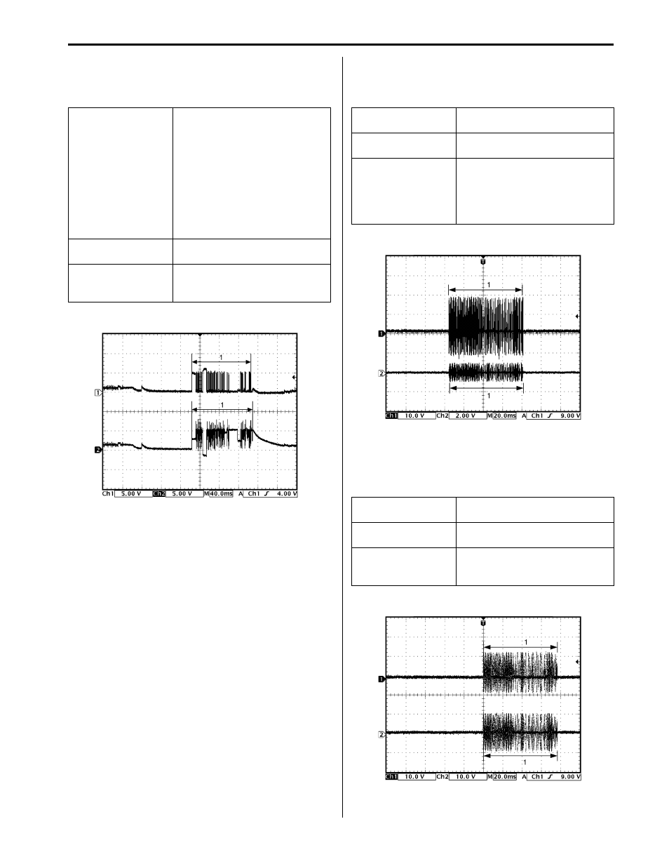
Reference waveform No. 1
Driver, passenger and rear end door antenna request
signals (Request signal (1) transmitted by each door
antenna when each door request switch is pushed)
Reference waveform No. 2
Center antenna signal
(Request signal (1) transmitted by center antenna when
each door request switch is pushed)
Reference waveform No. 3
Luggage room antenna signal
(Request signal (1) transmitted by luggage room
antenna when each door request switch is pushed)
Measurement
terminal
Driver side door antenna
• CH1: “G44-2” to “G44-9”
• CH2: “G44-1” to “G44-9”
Passenger side door antenna
• CH1: “G44-24” to “G44-9”
• CH2: “G44-23” to “G44-9”
Rear end door antenna
• CH1: “G44-4” to “G44-9”
• CH2: “G44-3” to “G44-9”
Oscilloscope setting CH1: 5 V/DIV, CH2: 5 V/DIV
TIME: 40 ms/DIV
Measurement
condition
Request switch of each door is
pushed with remote controller
carried
I4RS0BA50015-02
Measurement
terminal
CH1: “G44-6” to “G44-9”
CH2: “G44-5” to “G44-9”
Oscilloscope setting CH1: 10 V/DIV, CH2: 2 V/DIV
TIME: 20 ms/DIV
Measurement
condition
• Ignition knob switch of steering
lock unit is pushed
• Request switch of each door is
pushed with remote controller
carried
Measurement
terminal
CH1: “G44-8” to “G44-9”
CH2: “G44-7” to “G44-9”
Oscilloscope setting CH1: 10 V/DIV, CH2: 10 V/DIV
TIME: 20 ms/DIV
Measurement
condition
Request switch of each door is
pushed with remote controller
carried
I5JB0AA50024-03
I5JB0AA50025-02
10E-19 Keyless Start System:
Reference waveform No. 4
CAN communication signals
Reference waveform No. 5
Steering lock unit signal
(Signal (1) communicated between keyless start control
module and steering lock unit when measurement
condition described below applies)
Reference waveform No. 6
Driver and passenger side door lock switch signals.
(This signal indicates door lock status.)
In case the position of driver and passenger side door
lock is changed from the unlock to the lock.
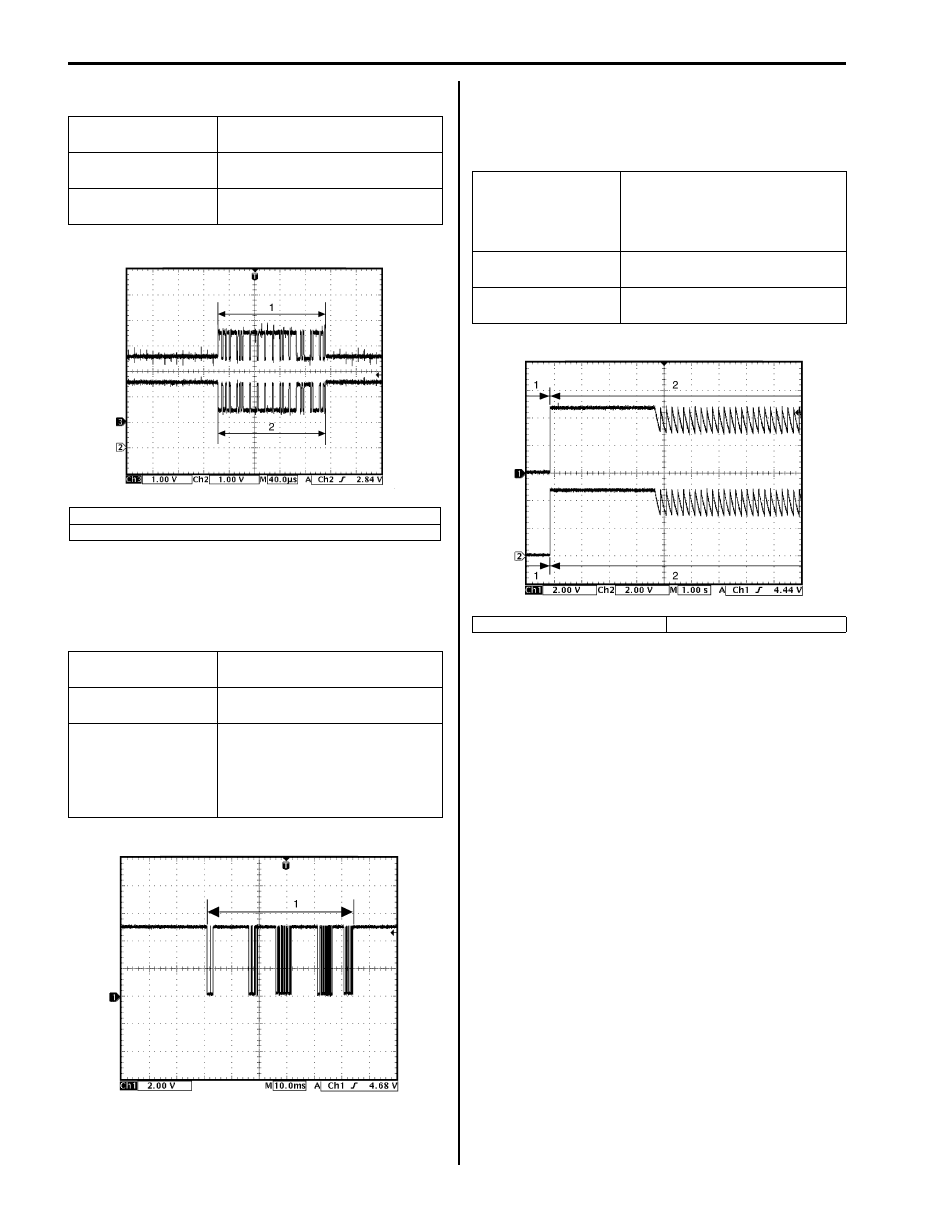
Measurement
terminal
CH1: “G44-19” to “G44-9”
CH2: “G44-18” to “G44-9”
Oscilloscope setting CH1: 1 V/DIV, CH2: 1 V/DIV
TIME: 40
µs/DIV
Measurement
condition
Ignition switch is at ON position
1. CAN communication line signal (high)
2. CAN communication line signal (low)
Measurement
terminal
CH1: “G44-29” to “G44-9”
Oscilloscope setting CH1: 2 V/DIV
TIME: 10 ms/DIV
Measurement
condition
• Ignition knob switch of steering
lock unit is pushed
• Request switch of each door is
pushed with remote controller
carried
I4RS0BA50018-02
I5JB0AA50026-02
Measurement
terminal
Driver side door lock switch
• CH1: “G44-33” to “G44-9”
Passenger side door lock switch
• CH2: “G44-37” to “G44-9”
Oscilloscope setting CH1: 2 V/DIV CH2: 2 V/DIV
TIME: 1 s/DIV
Measurement
condition
Press lock side of manual door
lock switch
1. Unlock signal
2. Lock signal
I5JB0AA50027-02
Keyless Start System: 10E-20
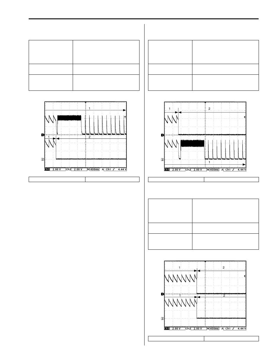
In case the position of passenger side door lock is
changed from the lock to the unlock when the position of
driver and passenger side door is at the lock
In case the position of driver side door lock is changed
from the lock to the unlock when the position of driver
and passenger side door is at the lock.
In case the position of driver and passenger side door
lock is changed from the lock to the unlock.
Measurement
terminal
Driver side door lock switch
• CH1: “G44-33” to “G44-9”
Passenger side door lock switch
• CH2: “G44-37” to “G44-9”
Oscilloscope setting CH1: 2 V/DIV CH2: 2 V/DIV
TIME: 400 ms/DIV
Measurement
condition
Driver door is at lock position and
passenger side door is at unlock
position
1. Lock signal
2. Unlock signal
I5JB0AA50028-02
Measurement
terminal
Driver side door lock switch
• CH1: “G44-33” to “G44-9”
Passenger side door lock switch
• CH2: “G44-37” to “G44-9”
Oscilloscope setting CH1: 2 V/DIV CH2: 2 V/DIV
TIME: 400 ms/DIV
Measurement
condition
Driver door is at unlock position
and passenger side door is at
lock position
1. Lock signal
2. Unlock signal
Measurement
terminal
Driver side door lock switch
• CH1: “G44-33” to “G44-9”
Passenger side door lock switch
• CH2: “G44-37” to “G44-9”
Oscilloscope setting CH1: 2 V/DIV CH2: 2 V/DIV
TIME: 400 ms/DIV
Measurement
condition
Driver door is at unlock position
and passenger side door is at
lock position
1. Lock signal
2. Unlock signal
I5JB0AA50029-02
I5JB0AA50030-03
Нет комментариевНе стесняйтесь поделиться с нами вашим ценным мнением.
Текст