Suzuki Grand Vitara JB627. Service manual — part 137
3-ii Table of Contents
CAN Communication System Description. . .3C-11
Schematic and Routing Diagram. . . . . ..3C-12
4WD Control System Wiring Circuit Diagram. 3C-12
Component Location . . . . . . . . . . .3C-14
Transfer Shift Control System Components
Location . . . . . . . . . . . . . . ..3C-14
Diagnostic Information and Procedures. . ..3C-15
4WD Control System Check . . . . . . . .3C-15
Transfer Position Indicator Operation Check . 3C-17
4WD Control System Operation Inspection . ..3C-17
Visual Inspection . . . . . . . . . . . ...3C-18
DTC Check. . . . . . . . . . . . . . 3C-19
DTC Clearance . . . . . . . . . . . . .3C-20
DTC Table. . . . . . . . . . . . . . .3C-21
Fail-Safe Table. . . . . . . . . . . . ..3C-22
Scan Tool Data . . . . . . . . . . . . .3C-22
Scan Tool Data Definitions. . . . . . . . 3C-23
4WD Control Symptom Diagnosis. . . . . .3C-24
Transfer Position Indicator Does Not Come
ON at Ignition Switch ON but Engine Stops. 3C-25
Transfer Position Indicator Remains ON
Steady at Ignition Switch ON . . . . . . ..3C-27
DTC C1213: Transfer Switch Circuit Open . ...3C-28
DTC C1214: Transfer Switch Circuit Short . ...3C-29
DTC C1223 / C1235: Transfer Shift Actuator
DTC C1224 / C1236: Transfer Shift Actuator
DTC C1227: 4L/N Switch Circuit Open . . . .3C-35
DTC C1228: 4L/N Switch Circuit Short . . . .3C-36
DTC C1230: Transfer Actuator Circuit
Malfunction. . . . . . . . . . . . . ..3C-38
DTC C1237: Center Differential Lock Switch
Circuit Open . . . . . . . . . . . . . 3C-39
DTC C1238: Center Differential Lock Switch
Circuit Short . . . . . . . . . . . . . 3C-41
DTC C1240: 4WD Control Module Power
Supply Circuit Malfunction . . . . . . . ..3C-42
DTC C1243: Internal Circuit Malfunction of
4WD Control Module. . . . . . . . . ...3C-43
DTC C1246: Clutch Pedal Position (CPP)
Switch Circuit Short. . . . . . . . . . .3C-44
DTC U1073: Control Module Communication
Bus Off . . . . . . . . . . . . . . . 3C-46
DTC U1100: Lost Communication with ECM . 3C-48
DTC U1101: Lost Communication with TCM . 3C-49
DTC U1121: Lost Communication with ABS /
Electronic Stability Program Hydraulic Unit /
Control Module. . . . . . . . . . . . 3C-50
Inspection of 4WD Control Module and Its
Circuits . . . . . . . . . . . . . . . 3C-50
Repair Instructions . . . . . . . . . . . 3C-53
Transfer Oil Level Check. . . . . . . . ...3C-53
Transfer Oil Change. . . . . . . . . . ..3C-53
Transfer Oil Seal Removal and Installation. ...3C-54
Transfer Switch Removal and Installation. . .3C-54
Transfer Switch Inspection. . . . . . . . 3C-55
4WD Control Module Removal and
Installation . . . . . . . . . . . . . ...3C-55
Transfer Assembly Dismounting and
Remounting. . . . . . . . . . . . . .3C-56
Transfer Assembly Components. . . . . ...3C-57
Transfer Assembly Disassembly and
Reassembly . . . . . . . . . . . . . 3C-58
Transfer Assembly Inspection. . . . . . ...3C-66
Input Gear Assembly, Counter Gear
Assembly, Front Output Shaft Assembly and
Rear Output Shaft Assembly Components . .3C-68
Input Gear Assembly Disassembly and
Reassembly . . . . . . . . . . . . . 3C-69
Counter Gear Assembly Disassembly and
Reassembly . . . . . . . . . . . . . 3C-70
Front Output Shaft Assembly Disassembly
and Reassembly . . . . . . . . . . . .3C-70
Rear Output Shaft Assembly Disassembly
and Reassembly . . . . . . . . . . . .3C-71
Specifications . . . . . . . . . . . . . .3C-72
Tightening Torque Specifications. . . . . ..3C-72
Special Tools and Equipment . . . . . . ...3C-72
Recommended Service Material . . . . . ...3C-72
Special Tool . . . . . . . . . . . . . ..3C-73
Propeller Shaft . . . . . . . . . . . 3D-1
Precautions. . . . . . . . . . . . . . ...3D-1
Propeller Shaft Caution . . . . . . . . . ...3D-1
General Description . . . . . . . . . . . .3D-1
Propeller Shaft Construction . . . . . . . ...3D-1
Diagnostic Information and Procedures . . . 3D-2
Propeller Shaft Symptom Diagnosis . . . . ...3D-2
Repair Instructions . . . . . . . . . . . ..3D-2
Propeller Shaft Joint Check. . . . . . . . .3D-2
Propeller Shaft Removal and Installation . . . 3D-2
Propeller Shaft Disassembly and Assembly . ...3D-4
Propeller Shaft Inspection . . . . . . . . ...3D-6
Specifications . . . . . . . . . . . . . ...3D-6
Tightening Torque Specifications. . . . . . 3D-6
Special Tools and Equipment . . . . . . . .3D-6
Recommended Service Material . . . . . . .3D-6
Special Tool . . . . . . . . . . . . . . 3D-6
Precautions: 3-1
Driveline / Axle
Precautions
Precautions
Precautions for Driveline / Axle
S6JB0B3000001
Differential Gear Oil Note
Refer to “Differential Gear Oil Note in Section 00”.
Fastener Caution
Refer to “Fastener Caution in Section 00”.
Precautions for Transfer
Refer to “Precautions in Diagnosing Trouble in Section 3C”.
3A-1 Drive Shaft / Axle: Front
Driveline / Axle
Drive Shaft / Axle
Front
General Description
Front Drive Shaft Construction
S6JB0B3111001
A constant velocity tripod joint is used on the differential side of both the right and left drive shaft assemblies. And, a
constant velocity ball joint is used on the wheel side of both the right and left drive shaft assemblies. The drive shaft
can slide through the tripod joint in the extension / contraction direction.
Diagnostic Information and Procedures
Front Drive Shaft Symptom Diagnosis
S6JB0B3114001
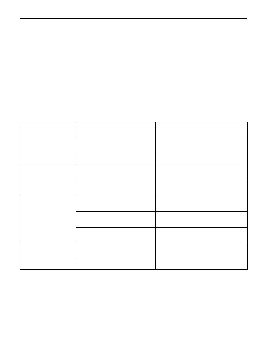
Condition
Possible cause
Correction / Reference Item
Abnormal noise: When
starting
Loose wheel nut(s)
Tighten wheel nut(s) referring to “Wheel
Removal and Installation in Section 2D”.
Loose drive shaft flange bolt(s)
Tighten drive shaft flange bolt(s) referring to
“Front Drive Shaft Assembly Removal and
Installation: Front”.
Broken or damaged wheel bearing
Replace referring to “Front Wheel Hub, Disc,
Nut and Bearing Check in Section 2B”.
Abnormal noise: When
making turns
Grease leakage from boot
Replace boot and apply grease referring to
“Front Drive Shaft Disassembly and Assembly:
Front”.
Worn or broken drive shaft joint
Replace drive shaft joint referring to “Front
Drive Shaft Disassembly and Assembly:
Front”.
Abnormal noise: When
running
Broken drive shaft joint
Replace drive shaft joint referring to “Front
Drive Shaft Disassembly and Assembly:
Front”.
Poorly lubricated or worn joint
Lubricate or replace joint referring to “Front
Drive Shaft Disassembly and Assembly:
Front”.
Loose drive shaft flange bolt(s)
Tighten drive shaft flange bolt(s) referring to
“Front Drive Shaft Assembly Removal and
Installation: Front”.
Vibration
Worn drive shaft joint
Replace drive shaft joint referring to “Front
Drive Shaft Disassembly and Assembly:
Front”.
Deformed drive shaft
Replace referring to “Front Drive Shaft
Disassembly and Assembly: Front”.
Drive Shaft / Axle: Front 3A-2
Repair Instructions
Front Drive Shaft Boot and Joint Check
S6JB0B3116001
• Check boot for tear. If even a small tear is found, replace with new one.
• Check drive shaft joint for wear, breakage, and any other damage. Replace if any abnormality is found.
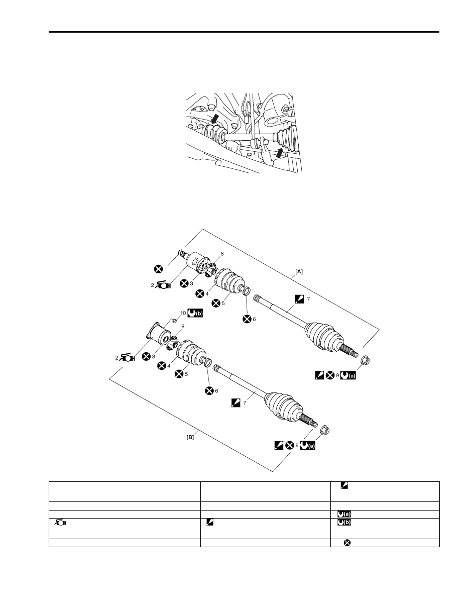
Front Drive Shaft Components
S6JB0B3116002
I5JB0A311001-01
I5JB0A311002-03
[A]: Right side drive shaft assembly
4. Boot band (Large)
9. Drive shaft nut
: After tightening nut, caulk nut
securely.
[B]: Left side drive shaft assembly
5. Boot (Differential side)
10. Front drive shaft flange nut
1. Circlip
6. Boot band (Small)
: 220 N
⋅m (22.0 kgf-m, 159.5 lb-ft)
2. Differential side joint (Constant velocity tripod joint)
: Apply yellow grease included in spare part to joint.
7. Wheel side joint assembly (Constant velocity
ball joint)
: Never disassemble.
: 80 N
⋅m (8.0 kgf-m, 58.0 lb-ft)
3. Snap ring
8. Tripod joint spider
: Do not reuse.
Нет комментариевНе стесняйтесь поделиться с нами вашим ценным мнением.
Текст