Opel Frontera UBS. Service manual — part 980
4A1–3
DIFFERENTIAL (FRONT)
Pinion Shaft Oil Seal
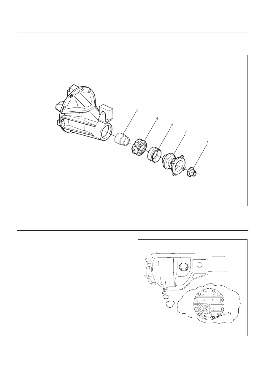
Pinion Shaft Oil Seal and Associated Parts
415RW015
Legend
(1) Flange Nut
(2) Flange
(3) Oil Seal
(4) Outer Bearing
(5) Collapsible Spacer
Removal
1. Raise the vehicle and support it at the frame.
The hoist must remain under the front axle housing.
2. Drain the front axle oil by loosening the drain plug(1).
412RS001
DIFFERENTIAL (FRONT)
4A1–4
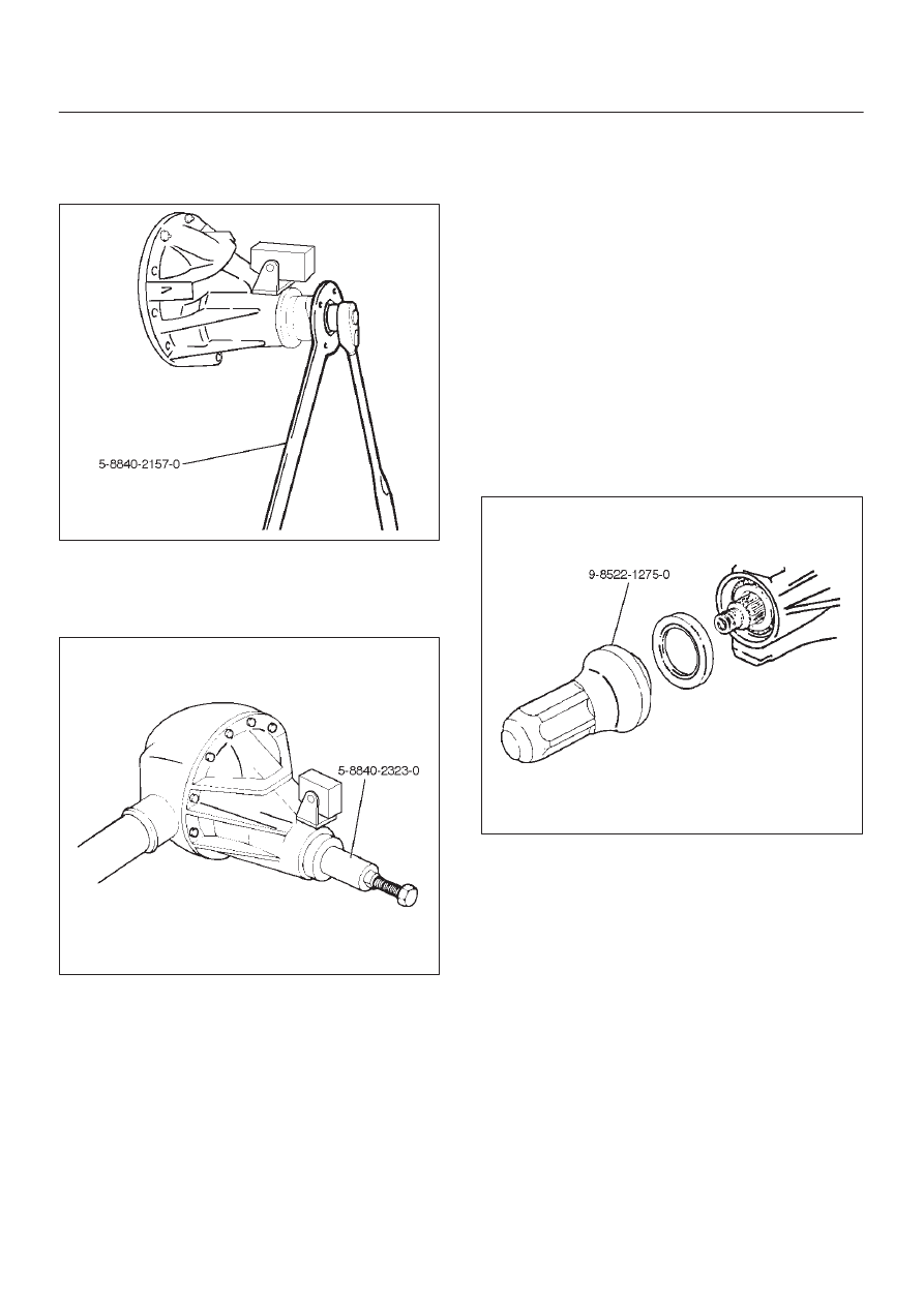
3. Remove the front propeller shaft. Refer to Front
Propeller Shaft in this section.
4. Remove flange nut by using pinion flange holder
5–8840–2157–0.
425RW045
5. Remove flange.
6. Remove oil seal.
7. Remove outer bearing by using remover
5–8840–2323–0.
415RW022
8. Remove collapsible spacer.
Inspection and Repair
Make necessary correction or parts replacement if wear,
damage, corrosion or any other abnormal conditions are
found through inspection.
Check the following parts:
1. Seal surface of the pinion.
2. Cage bore for burns.
Installation
1. Install collapsible spacer. Discard the used
collapsible spacer and install a new one.
2. Install outer bearing.
NOTE: Do not drive in, but just temporarily set in the outer
bearing by hand, which should be indirectly pressed in
finally by tightening the flange nut.
3. Install oil seal, use oil seal installer 9–8522–1275–0 to
install a new oil seal that has been soaked in axle
lubricant.
415RW021
4. Install flange.
5. Install flange nut, refer to Differential Assembly for
flange nut reassembly in this section.
NOTE: Discard the used nut and install a new one.
4A1–5
DIFFERENTIAL (FRONT)
Front Drive Axle Assembly
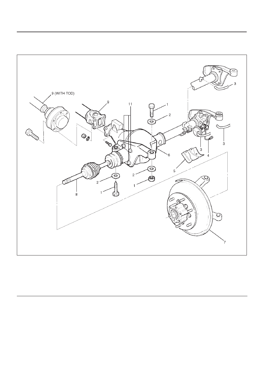
Front Drive Axle Assembly and Associated Parts
412RY00001
Legend
(1) Mounting Bolt and Nut
(2) Washer and Spacer
(3) Breather Hose
(4) Shift Switch Connector (with Shift on the Fly)
(5) Protector (with Shift on the Fly)
(6) Front Axle Case Assembly and Front Drive
Shaft Assembly (LH side)
(7) Hub Assembly (Disc, Back Plate and Knuckle)
(8) Front Drive Shaft Assembly (RH side)
(9) Propeller Shaft
(10) Bolt
Removal
1. Jack up the vehicle and support it using jack stands.
2. Remove the tire and wheel.
DIFFERENTIAL (FRONT)
4A1–6
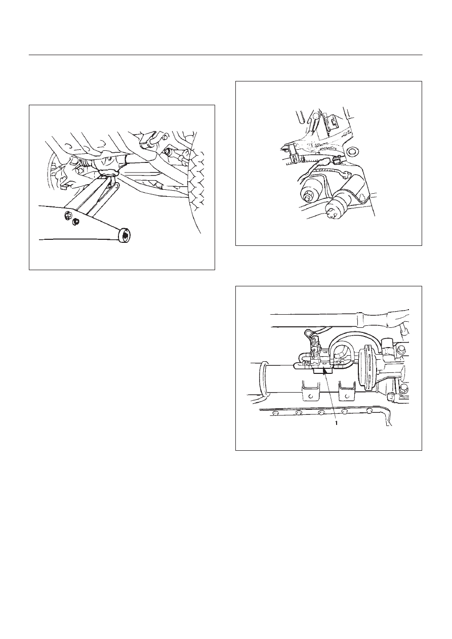
3. Remove the drain bolt to drain differential oil.
NOTE:
a. During the work, be sure that the diff case is
supported by the jack.
412RS003
b. Remove the brake caliper fixing bolt and hang the
caliper. Refer to Front Disc Brake Caliper Assembly
in Brake section.
c. Remove the antilock brake system speed sensor (if
equipped). Refer to Front Wheel Speed Sensor in
Brakes section.
4. Remove the hub assembly (Disc, back plate and
knuckle), refer to Front Hub and Disc in this section.
5. Disconnect the knuckle and the suspension arm.
Refer to Suspension section.
6. Remove steering link and arm assembly, refer to
Steering Linkage in Steering section.
7. Remove suspension crossmember.
8. Remove propeller shaft, refer to Front Propeller Shaft
in this section.
9. Remove protector (Shift on the fly model).
10. Remove the hose clip.
11. Disconnect breather hose from front drive axle tube.
(and disconnect housing : Shift on the fly model).
12. Disconnect vacuum hose from actuator (Shift on the
fly model).
13. Disconnect shift switch connector (Shift on the fly
model).
412RS031
14. Remove VSV assembly (1) (Shift on the fly model).
NOTE: Be sure not to remove hose and connector from
VSV asm.
412RW002
Нет комментариевНе стесняйтесь поделиться с нами вашим ценным мнением.
Текст