Opel Frontera UBS. Service manual — part 981
4A1–7
DIFFERENTIAL (FRONT)
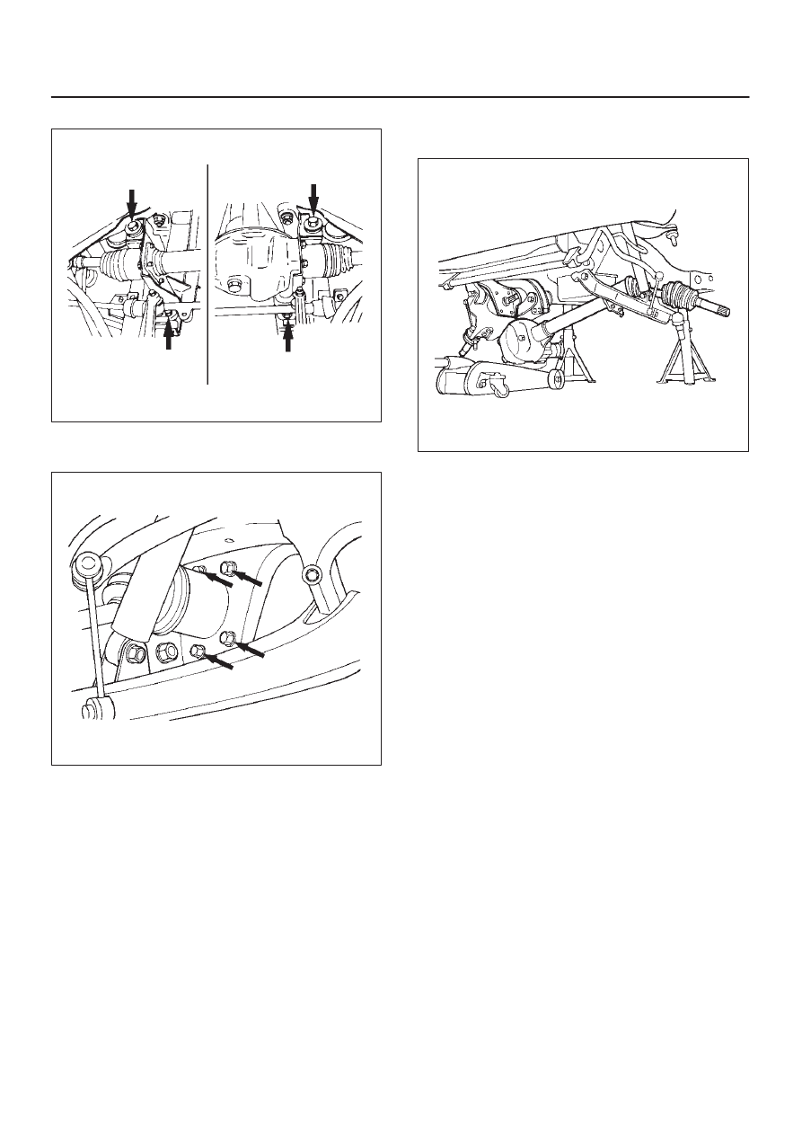
15. Remove mounting bolt and nut.
412RS004
16. Remove washer and spacer.
17. Remove the mounting bracket fixing bolt.
412RS005
18. Lower the vehicle and disconnect the RH front drive
shaft assembly, then remove the front axle case
assembly and front drive shaft assembly (LH).
412RS006
19. Remove front drive shaft assembly (RH).
Installation
1. Install front drive shaft assembly (RH) and lay the
assembly on the lower arm.
2. Install front axle case assembly and front drive shaft
assembly (LH) and place the axle case on the jack,
connect to the front drive shaft assembly (RH) before
installing to the vehicle.
3. Install bolt and tighten the mounting bracket fixing bolt
to the specified torque.
Torque: 116 N·m (11.8kg·m/85 lb ft)
4. Install washer and spacer.
DIFFERENTIAL (FRONT)
4A1–8
5. Tighten the mounting bolt and nut to the specified
torque.
Torque: 152 N·m (15.5kg·m/112 lb ft)
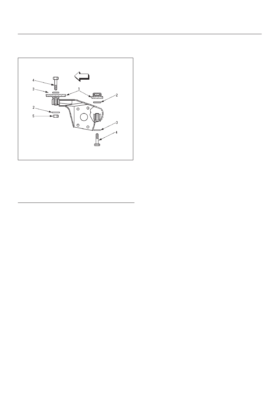
412RW005
Legend
(1) Frame
(2) Spacer
(3) Washer
(4) Bolt
(5) Nut
6. Install VSV assembly and tighten nuts to specified
torque (Shift on the fly model).
Torque: 8 N·m (0.8kg·m/69 lb in)
7. Install the shift switch connector (Shift on the fly
model).
NOTE: Be careful not to permit the entry of dust into the
connector.
8. Install the actuator side of vacuum hose (Shift on the
fly model).
NOTE: Be careful not to permit the entry of dust into the
hose.
9. Connect breather hose and install the hose clip.
10. Install protector and tighten bolts to specified torque
(Shift on the fly model).
Torque: 26 N·m (2.7kg·m/20 lb ft)
11. Install propeller shaft, refer to Front Propeller Shaft in
this section.
12. Install suspension crossmember.
13. Steering link and arm assembly, refer to Steering
Linkage in Steering section.
14. Install hub assembly (Disc, back plate and knuckle),
refer to Front Hub and Disc in this section.
4A1–9
DIFFERENTIAL (FRONT)
Differential Assembly
Disassembled View
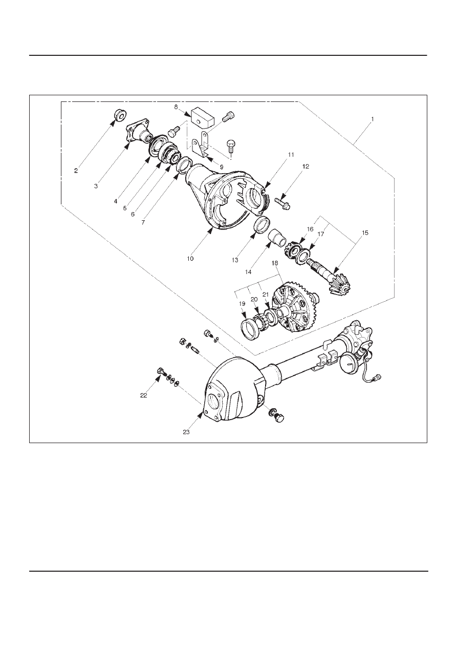
415RW001
Legend
(1) Differential Assembly
(2) Flange Nut
(3) Flange
(4) Dust Cover
(5) Oil Seal
(6) Outer Bearing
(7) Outer Bearing Outer Race
(8) Damper
(9) Bracket
(10) Differential Carrier
(11) Bearing Cap
(12) Bolt
(13) Inner Bearing Outer Race
(14) Collapsible Spacer
(15) Pinion Gear
(16) Inner Bearing
(17) Adjust Shim
(18) Diff Cage Assembly
(19) Side Bearing Outer Race
(20) Side Bearing
(21) Adjust Shim
(22) Bolt
(23) Axle Case
DIFFERENTIAL (FRONT)
4A1–10
Disassembly
1. Remove differential carrier fixing bolt.
2. Remove differential assembly.
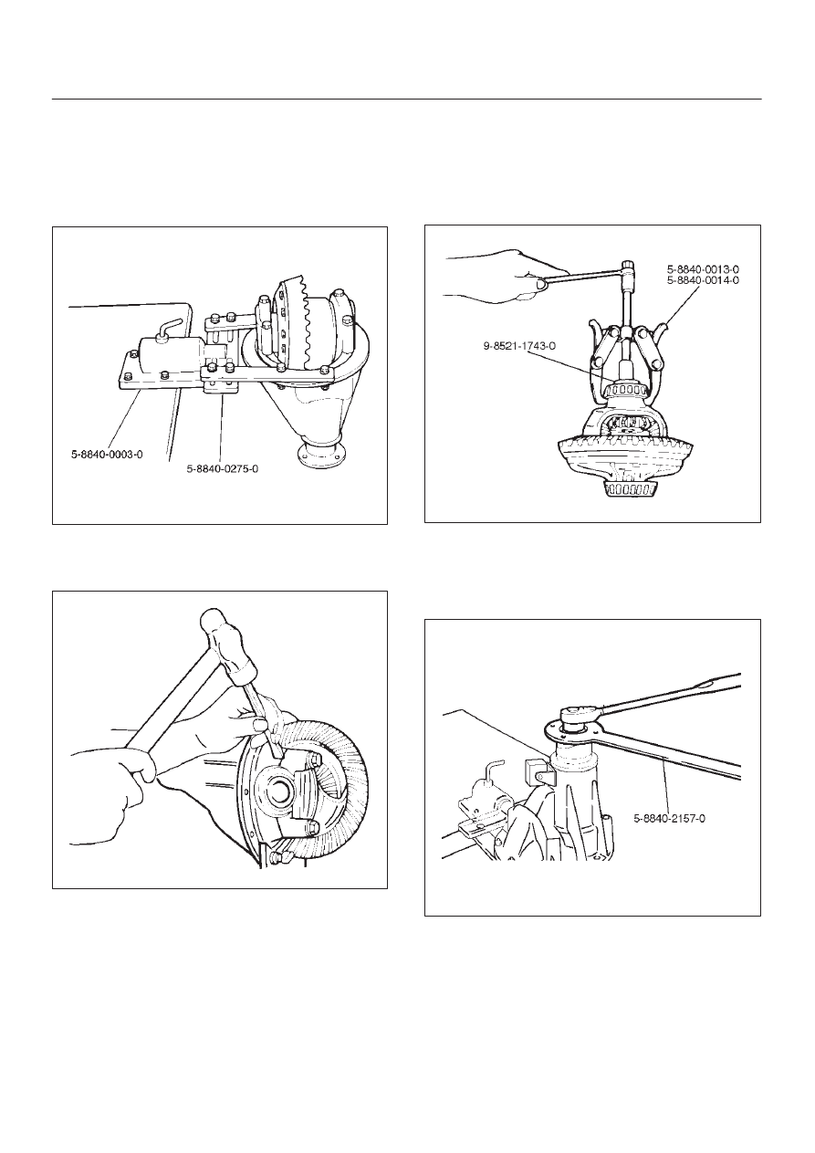
3. Using holding fixture 5–8840–0275–0 and holding
fixture base 5–8840–0003–0, fix the differential
assembly to the bench.
425RW046
4. Remove bearing cap bolt.
5. Apply a setting mark to the side bearing cap and the
differential carrier then remove bearing cap.
425RS009
6. Remove differential cage assembly.
7. Remove side bearing outer race, after removal, keep
the right and left hand side bearing assemblies
separate to maintain inner and outer race
combinations.
8. Remove side bearing, using remover
5–8840–0013–0, 5–8840–0014–0 and adapter
9–8521–1743–0.
415RW023
9. Remove adjust shim, note the thickness and position
of the shims removed.
10. Remove the flange nut using holding wrench
5–8840–2157–0 after raising up its staked parts
completely.
425RW047
11. Remove flange.
Нет комментариевНе стесняйтесь поделиться с нами вашим ценным мнением.
Текст