Opel Frontera UBS. Service manual — part 2826
8D–504
WIRING SYSTEM
Power Seat
General Description
The circuit consists of power seat switch, front tilt
motor (driver’s seat only), rear tilt motor (driver’s seat
only), slide motor and recliner motor.
Power seat switch has a tilt and slide switch and a
recliner switch. The motor built in the seat can be
actuated by operating these switches to move the
seat to desired position, independent of position of
starter switch.
WIRING SYSTEM
8D–505
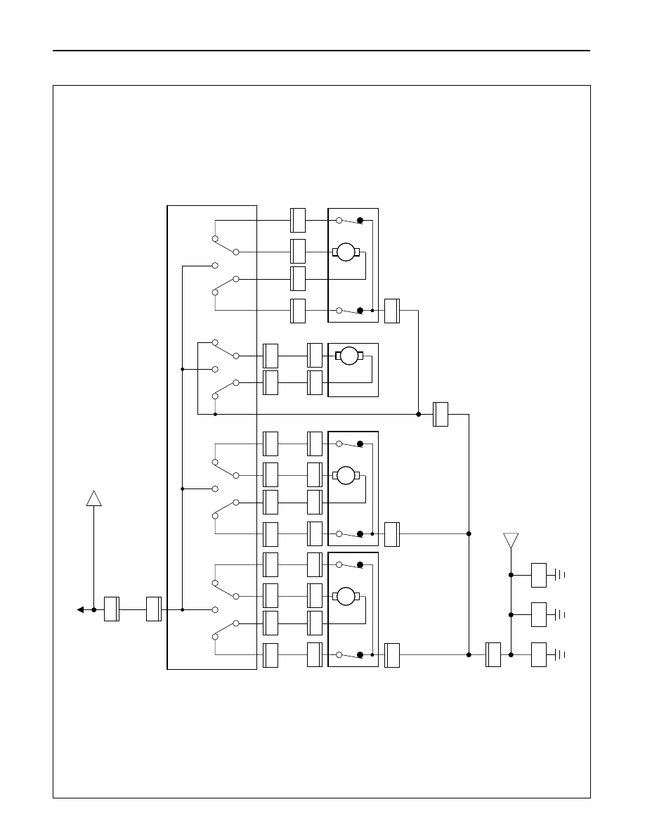
Circuit Diagram (RHD)-1
D08RW640
A
H-57
C/B-2
3.0
B/L
3.0
B/L
2.0
R
1
T-
2
PO
WER SEA
T SW
-RH
1
2.0
B
2.0
B
2.0
B
2.0
B
2.0
B
2.0
B
M
T-
1
1
1.25
Y
1.25
Y/B
T-
1
T-
4
T-
4
6
1.25
Y/R
1.25
Y/W
T-
1
3
T-
1
UP
DO
WN
8
T-
3
RECLINER
MO
T
OR & SW
-LH
DRIVER'S SEA
T
TIL
T MO
T
O
R
& SW
-FR
T
3
B
M
T-
1
5
T-
1
10
1.25
L/W
FR
T
R
R
1.25
G/R
SLIDE MO
T
O
R
-LH
T-
3
2
T-
3
1
2
1
M
T-
1
2
1.25
L
1.25
L/B
T-
1
T-
6
T-
6
7
1.25
L/R
1.25
G
T-
1
4
T-
1
UP
DO
WN
9
T-
5
DRIVER'S SEA
T
TIL
T MO
T
O
R
& SW
-RR
3
T-
5
2
T-
5
1
2
1
M
T
-11
3
1.25
W
1.25
B/W
T
-11
6
1.25
BR
1.25
LG
T
-11
2
T
-11
5
T
-11
4
H-57
BOD
Y
-CTR
BOD
Y
-LH
BOD
Y
-RH
4
T-
2
2
B-26
B-2
B-18
T-
7
1
T-
7
2
FR
T
R
R
8D–506
WIRING SYSTEM
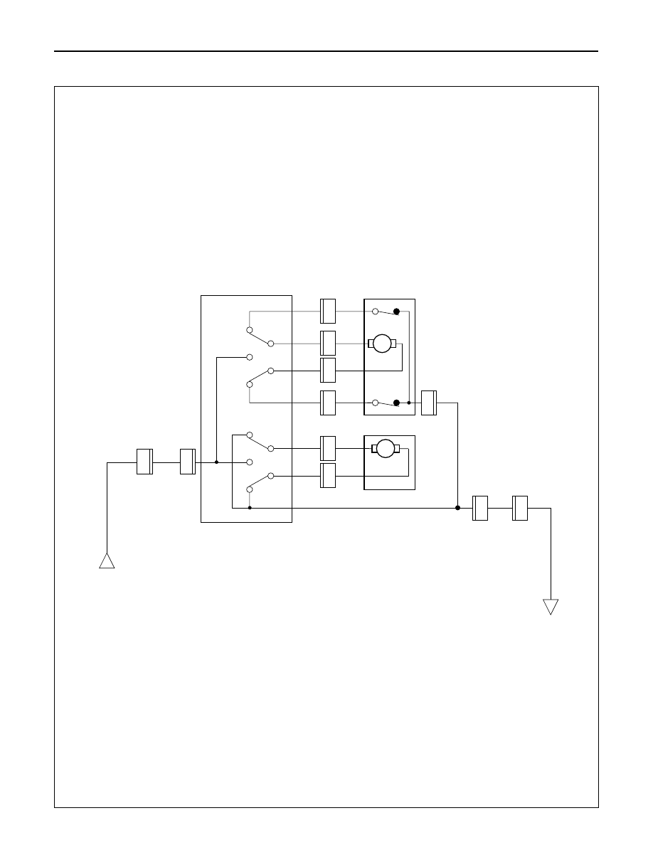
Circuit Diagram (RHD)-2
D08RW641
A
H-58
3.0
B/L
2.0
R
1
T-
9
PO
WER SEA
T SW
-LH
1
M
T
-13
1
T
-13
2
1.25
G
FR
T
R
R
F
R
T
RR
T-
9
2.0
B
2.0
B
2.0
B
2
H-58
4
1.25
G/R
M
T
-12
3
1.25
W
1.25
B/W
T
-12
6
1.25
BR
1.25
LG
T
-12
2
T
-12
5
T
-12
SLIDE MO
T
O
R
-RH
RECLINER
MO
T
OR & SW
-RH
4
B
WIRING SYSTEM
8D–507
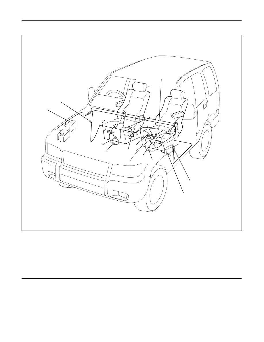
Parts Location (RHD)
Legend
(1) T-6
(2) T-4
(3) T-1
(4) B-2
(5) Fuse Box
(6) H-58
(7) B-26
(8) T-9
(9) T-13
(10) T-12
(11) H-57
(12) T-7
(13) Relay and Fuse Box
(14) B-18
D08RW996
1
3
4
5
6
8
7
11
12
9
13
10
14
2
Нет комментариевНе стесняйтесь поделиться с нами вашим ценным мнением.
Текст