Opel Frontera UBS. Service manual — part 2827
8D–508
WIRING SYSTEM
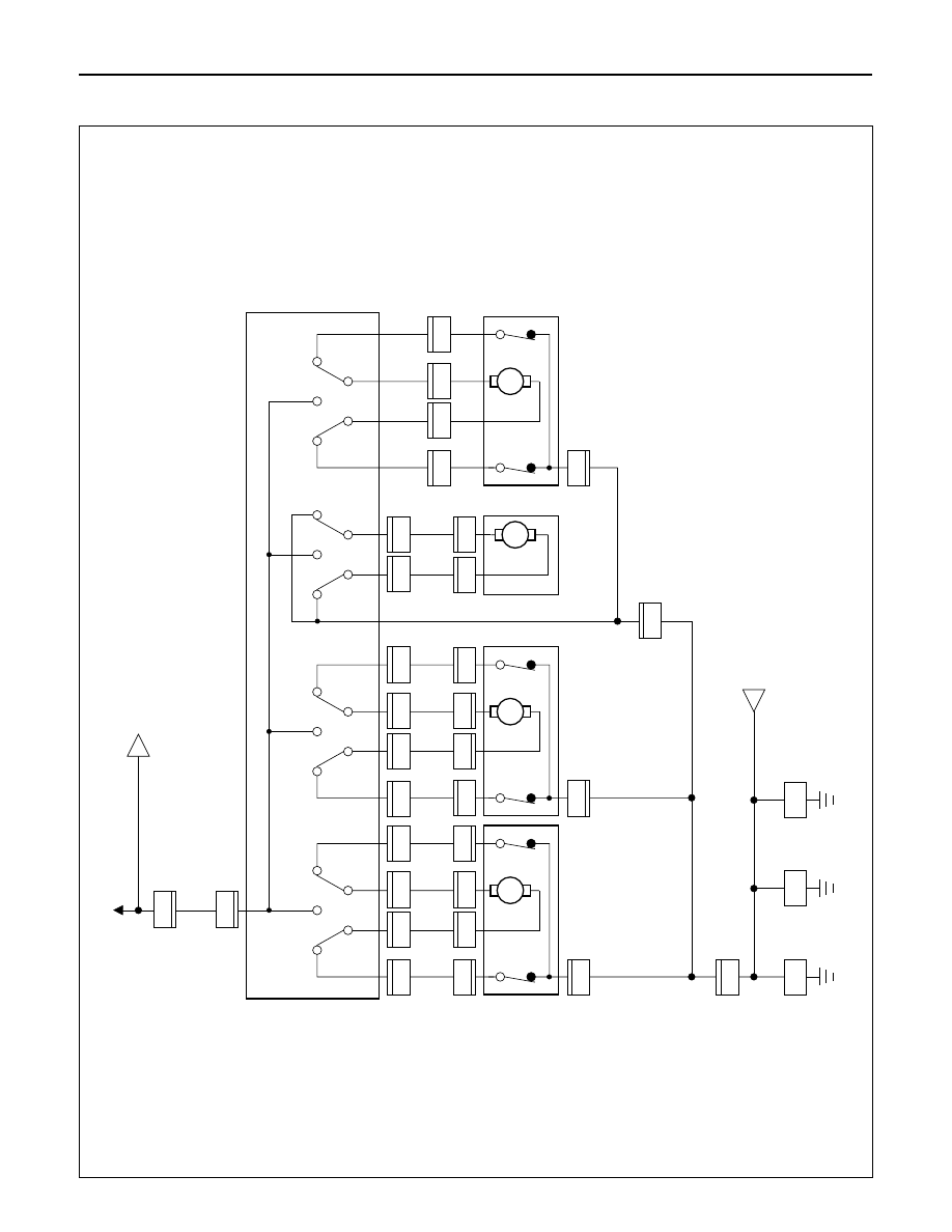
Circuit Diagram (LHD)-1
D08RW951
A
H-57
C/B-2
3.0
B/L
3.0
B/L
2.0
R
1
T-
2
POWER SEA
T
SW
-LH
1
2.0
B
2.0
B
2.0
B
2.0
B
M
T-
1
1
1.25
Y
1.25
Y/B
T-
1
T-
4
T-
4
6
1.25
Y/R
1.25
Y/W
T-
1
3
T-
1
UP
DOWN
8
T-
3
RECLINER
MOT
OR & SW
-LH
DRIVER'S SEA
T
TIL
T
MOT
OR
& SW
-FR
T
3
B
M
T-
1
5
T-
1
10
1.25
L/W
FR
T
R
R
1.25
G/R
SLIDE MOT
OR
-LH
T-
3
2
T-
3
1
2
1
M
T-
1
2
1.25
L
1.25
L/B
T-
1
T-
6
T-
6
7
1.25
L/R
1.25
G
T-
1
4
T-
1
UP
DOWN
9
T-
5
DRIVER'S SEA
T
TIL
T
MOT
OR
& SW
-RR
3
T-
5
2
T-
5
1
2
1
M
T-
1
1
3
1.25
W
1.25
B/W
T-
1
1
6
1.25
BR
1.25
LG
T-
1
1
2
T-
1
1
5
T-
1
1
4
H-57
BODY
-LH
4
T-
2
2
B-18
BODY
-CTR
B-26
BODY
-RH
B-2
T-
7
1
T-
7
2
FR
T
R
R
WIRING SYSTEM
8D–509
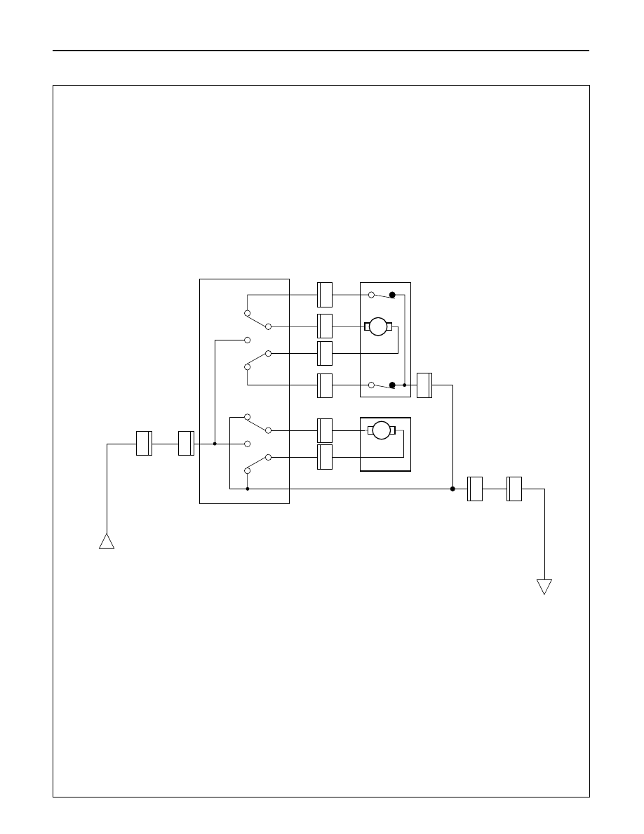
Circuit Diagram (LHD)-2
D08RW952
A
H-58
3.0
B/L
2.0
R
1
T-
9
POWER SEA
T
SW
-RH
1
M
T-
1
3
1
T-
1
3
2
1.25
G
FR
T
R
R
F
R
T
RR
T-
9
2.0
B
2.0
B
2.0
B
2
H-58
4
1.25
G/R
M
T-
1
2
3
1.25
W
1.25
B/W
T-
1
2
6
1.25
BR
1.25
LG
T-
1
2
2
T-
1
2
5
T-
1
2
SLIDE MOT
OR
-RH
RECLINER
MOT
OR & SW
-RH
4
B
8D–510
WIRING SYSTEM
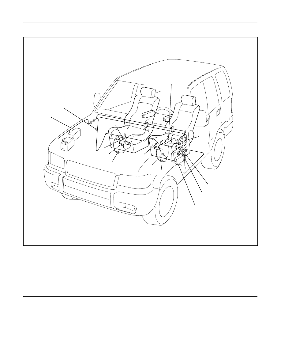
Parts Location (LHD)
Legend
(1) T-6
(2) T-4
(3) T-1
(4) B-18
(5) Fuse Box
(6) H-57
(7) T-7
(8) B-26
(9) H-58
(10) T-9
(11) T-13
(12) Relay and Fuse Box
(13) B-2
(14) T-12
D08RW994
2
1
3
4
5
6
7
8
9
10
11
12
14
13
WIRING SYSTEM
8D–511
1.
2.
3.
4.
5.
1.
2.
3.
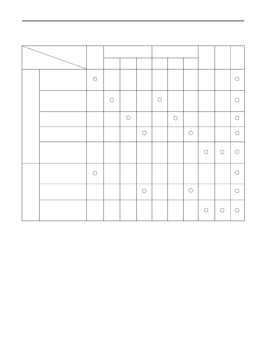
Cable
har-
ness
Check point
Trouble mode
Driver
seat
Passen-
ger
seat
Reclin-
ing
motor
Reclin-
ing
SW
Tilt & slide motor
Slide
RR tilt
FRT tilt
Tilt & slide SW
Slide
RR tilt
FRT tilt
Circuit
breaker
(30A)
Power seat does
not operate at any
direction
Front tilt
mechanism does
not operate
Rear tilt mechanism
does not operate
Sliding mechanism
does not operate
Reclining
mechanism does
not operate
Power seat does
not operate at any
direction
Sliding mechanism
does not operate
Reclining
mechanism does
not operate
Diagnosis
Quick Chart for Check Points
Нет комментариевНе стесняйтесь поделиться с нами вашим ценным мнением.
Текст