Opel Frontera UBS. Service manual — part 1897
POWER STEERING 2A – 13
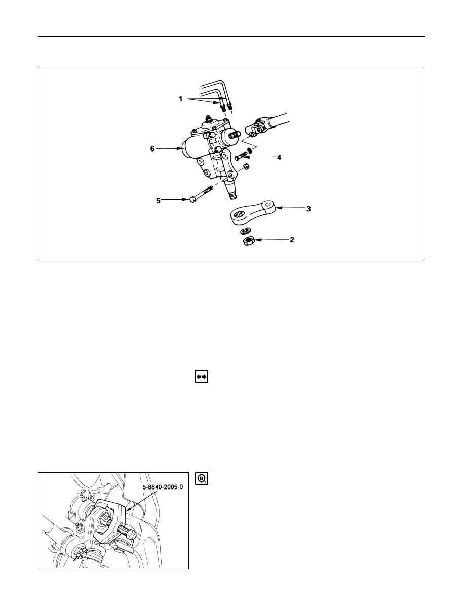
STEERING GEAR
Removal Steps
1.
Pipe
2.
Nut
3.
Pitman arm
4.
Universal joint bolt
5.
Gear box mounting bolt and nut
6.
Gear box
Installation Steps
6.
Gear box
5.
Gear box mounting bolt and nut
4.
Universal joint bolt
3.
Pitman arm
2.
Nut
1.
Pipe
REMOVAL
Preparation:
1)
Remove the stone guard.
2)
Remove the lower fan shroud. Refer to “Engine
cooling” in section 6B1.
3)
Disconnect stabilizer bar at the stabilizer links.
Loosen stabilizer bracket fixing nuts.
1.
Pipe
2.
Nut
3.
Pitman Arm
Pitman arm remover: 5-8840-2005-0 (J-29107)
These steps are based on the LHD model.
2A – 14 POWER STEERING
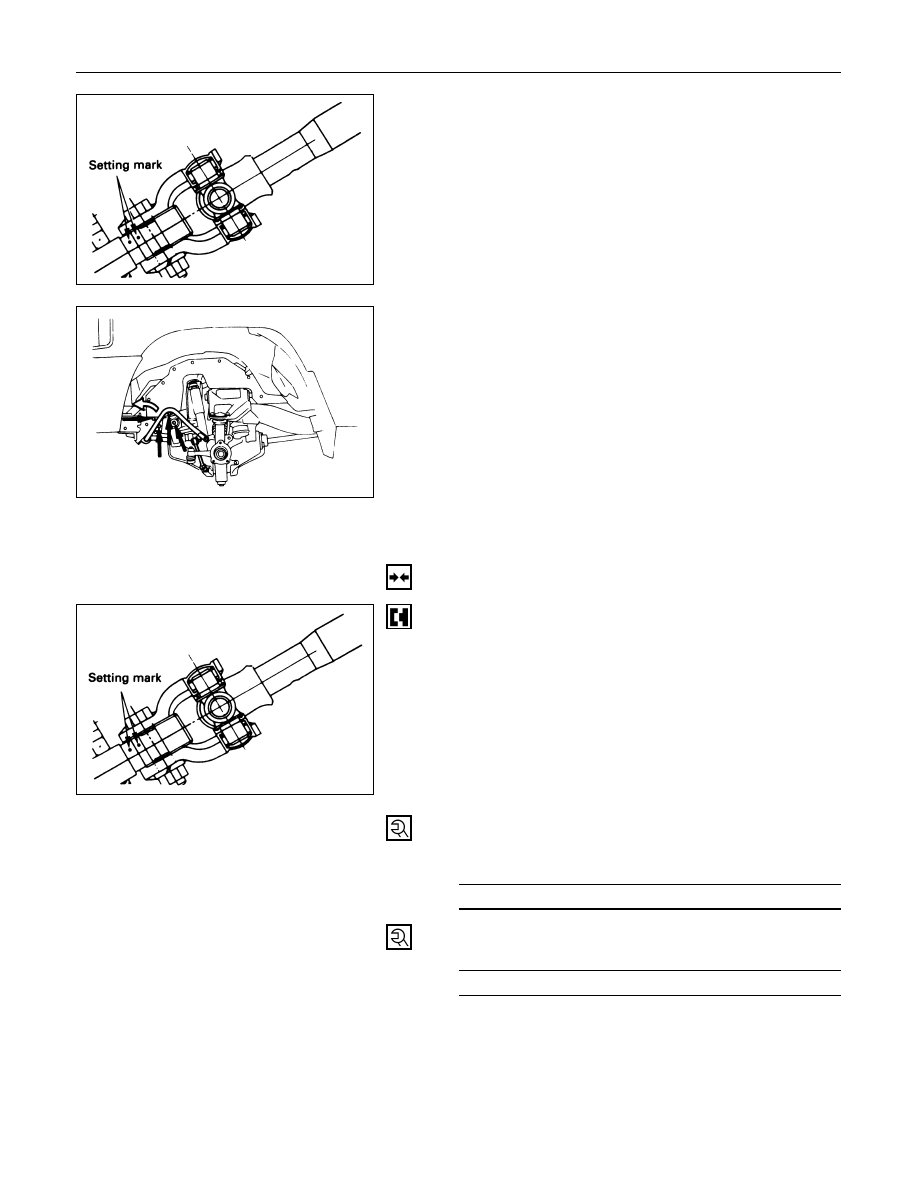
4.
Universal Joint Bolt
Make a setting mark across the coupling flange and
worm shaft to ensure reassembly of the parts in the
original position.
5.
Gear Box Mounting Bolt and Nut
Push the stabilizer bar aside and remove the bolts
and nuts.
6.
Gear Box
INSTALLATION
6.
Gear Box
Align the setting marks made at removal.
5.
Gear Box Mounting Bolt and Nut
Gear Box Mounting
Bolt and Nut Torque
N·m (kg·m/lb·ft)
44 (4.5 / 33)
4.
Universal Joint Bolt
Coupling Clamp Bolt Torque
N·m (kg·m/lb·ft)
25 (2.5 / 18)
POWER STEERING 2A – 15
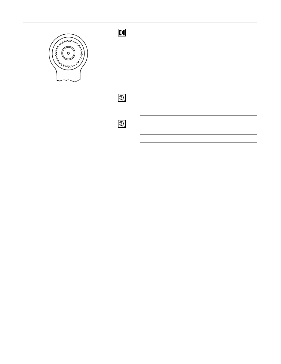
3.
Pitman Arm
Align the notched tooth.
2
Nut
Pitman Arm Nut Torque
N·m (kg·m/lb·ft)
216 (22.0 / 159)
1.
Pipe
Pipe Nut Torque
N·m (kg·m/lb·ft)
44 (4.5 / 33)
2A – 16 POWER STEERING
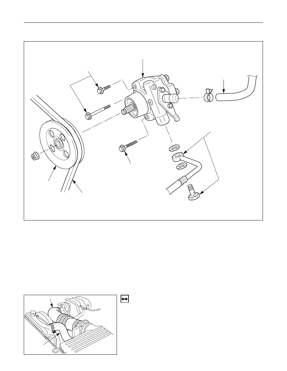
POWER STEERING PUMP (6VD1, 6VE1 Engine Models)
6
5
3
4
5
1
2
Removal Steps
1.
Drive belt
2.
Pulley
3.
Hose, suction
4.
Hose, flexible
5.
Bolt
6.
Pump assembly
Installation Steps
6.
Pump assembly
5.
Bolt
4.
Hose, flexible
3.
Hose, suction
2.
Pulley
1.
Drive belt
REMOVAL
Preparation:
•
Drain the engine coolant.
•
Place a drain pan below the pump.
•
Remove the air cleaner duct (1) and the radiator
upper hose (2).
436RW006
1
2
436RW005
Нет комментариевНе стесняйтесь поделиться с нами вашим ценным мнением.
Текст