Opel Frontera UBS. Service manual — part 1895
FRONT END ALIGNMENT 2A – 5
Position of shim
Camber angle
Caster angle
Front side
Rear side
When added
When removed
Decreases
Decreases
When removed
When added
Increases
Increases
Caster shim
When removed
Unchanged
Decreases
When added
Unchanged
Increases
When added
Decreases
Unchanged
Camber shim
When removed
Increases
Unchanged
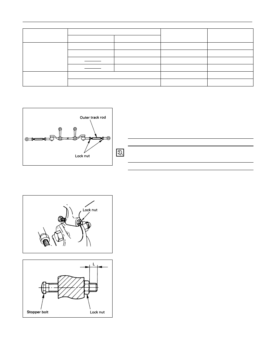
TOE-IN ADJUSTMENT
1.
To adjust the toe-in angle, loosen the lock nuts on the
outer track rods and turn the outer track rods. Turn
both rods the same amount, to keep the steering
wheel centered.
Toe-in
mm(in)
0 ± 2 (0 ± 0.08)
2.
Tighten the lock nut to the specified torque.
Lock Nut Torque
N·m (kg·m/lb·ft)
118 (12.0 / 87)
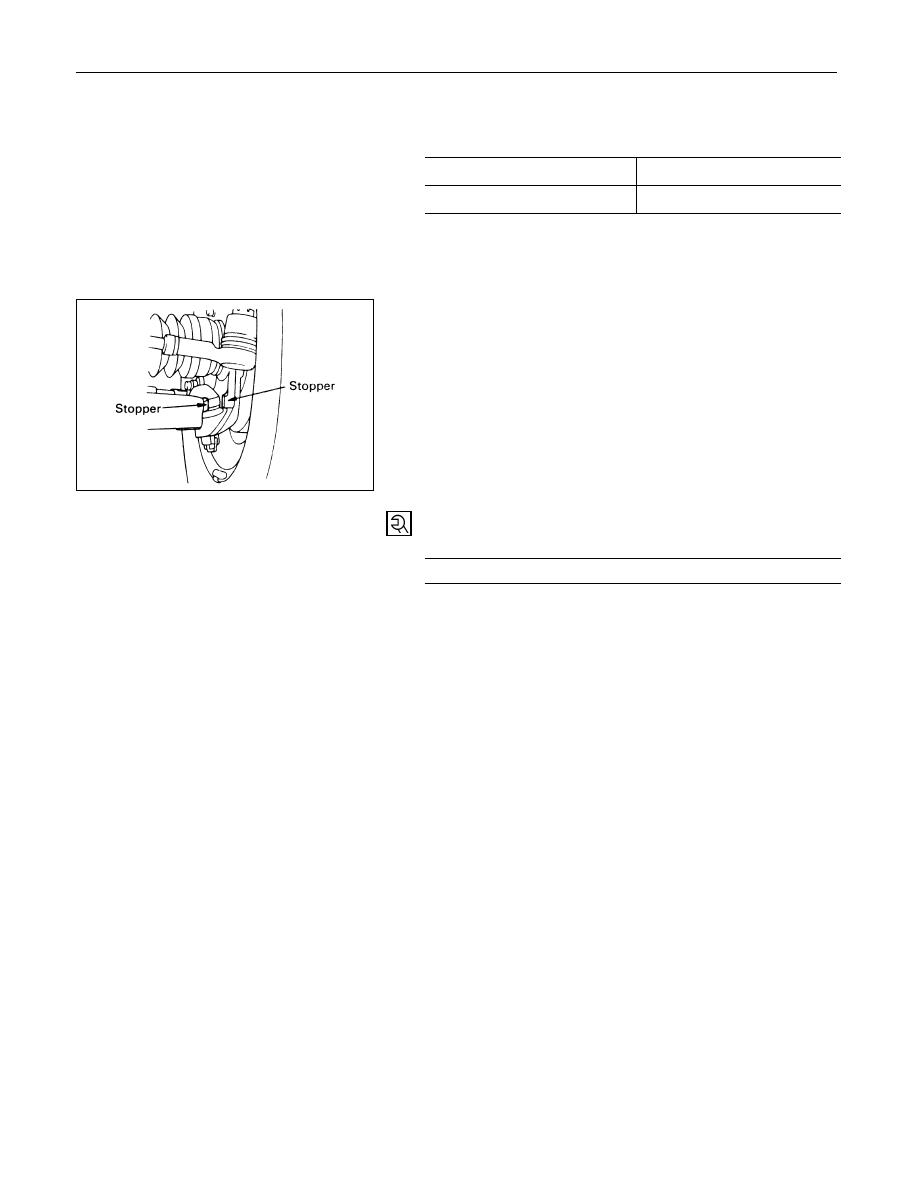
MAXIMUM STEERING ANGLE
ADJUSTMENT
The maximum steering angle of the front wheels can be
adjusted with the stopper bolts under the frame side
members.
1.
Position each front wheel on the turning radius gauge
in a straight-ahead position.
2.
Set the parking brake firmly.
3.
Adjust the inside wheel angle of each side with the
stopper bolts.
NOTE:
The maximum protruding length (L) of stopper bolt from
the lock nut should be 10 mm (0.4 in) or less.
6.
Tighten the lock nut to the specified torque.
Lock Nut Torque
N·m (kg·m/lb·ft)
23 (2.3 / 17)
2A – 6 FRONT END ALIGNMENT
4.
Similarly adjust the inside wheel angle of the other
side with stopper bolt.
Maximum Steering Angle
Inside wheel
34°
+0°
-2°
Outside wheel
32°
NOTE:
Maximum steering angles should be set after adjusting
front wheel alignment.
5.
If the stop between the lower link end and the knuckle
comes ahead of the stopper bolt, adjust the stopper
bolt so that inner stopper bolt touches the drop arm
(relay lever).
POWER STEERING 2A – 7
SECTION 2A
POWER STEERING
CONTENTS
PAGE
General Description . . . . . . . . . . . . . . . . . . . . . . . . . . . 2A – 8
Power Steering Gear . . . . . . . . . . . . . . . . . . . . . . . . ... 2A – 9
Hydraulic Pump . . . . . . . . . . . . . . . . . . . . . . . . . . ... 2A – 9
Pressure Switch (6VD1, 6VE1 Engine). . . . . . . . . . . . . . . . . ... 2A – 9
Power Steering System Test . . . . . . . . . . . . . . . . . . . . . . .. 2A – 10
On-Vehicle Service. . . . . . . . . . . . . . . . . . . . . . . . . . ... 2A – 12
Bleeding The Power Steering System. . . . . . . . . . . . . . . . . ... 2A – 12
Flushing The Power Steering System . . . . . . . . . . . . . . . . . ... 2A – 12
Steering Gear . . . . . . . . . . . . . . . . . . . . . . . . . . . ... 2A – 13
Power Steering Pump (6VD1, 6VE1 Engine Models) . . . . . . . . . . . ... 2A – 16
Power Steering Pump (4JG2 Engine Model) . . . . . . . . . . . . . . . 2A – 18
Power Steering Pump (4JX1 Engine Model). . . . . . . . . . . . . . . . 2A – 20
Unit Repair. . . . . . . . . . . . . . . . . . . . . . . . . . . . . . 2A – 22
Steering Gear . . . . . . . . . . . . . . . . . . . . . . . . . . . ... 2A – 22
Power Steering Pump (6VD1, 6VE1 Engine Models) . . . . . . . . . . . ... 2A – 28
Power Steering Pump (4JG2 Engine Model) . . . . . . . . . . . . . . . 2A – 32
Power Steering Pump (4JX1 Engine Model). . . . . . . . . . . . . . . . 2A – 36
2A – 8 POWER STEERING
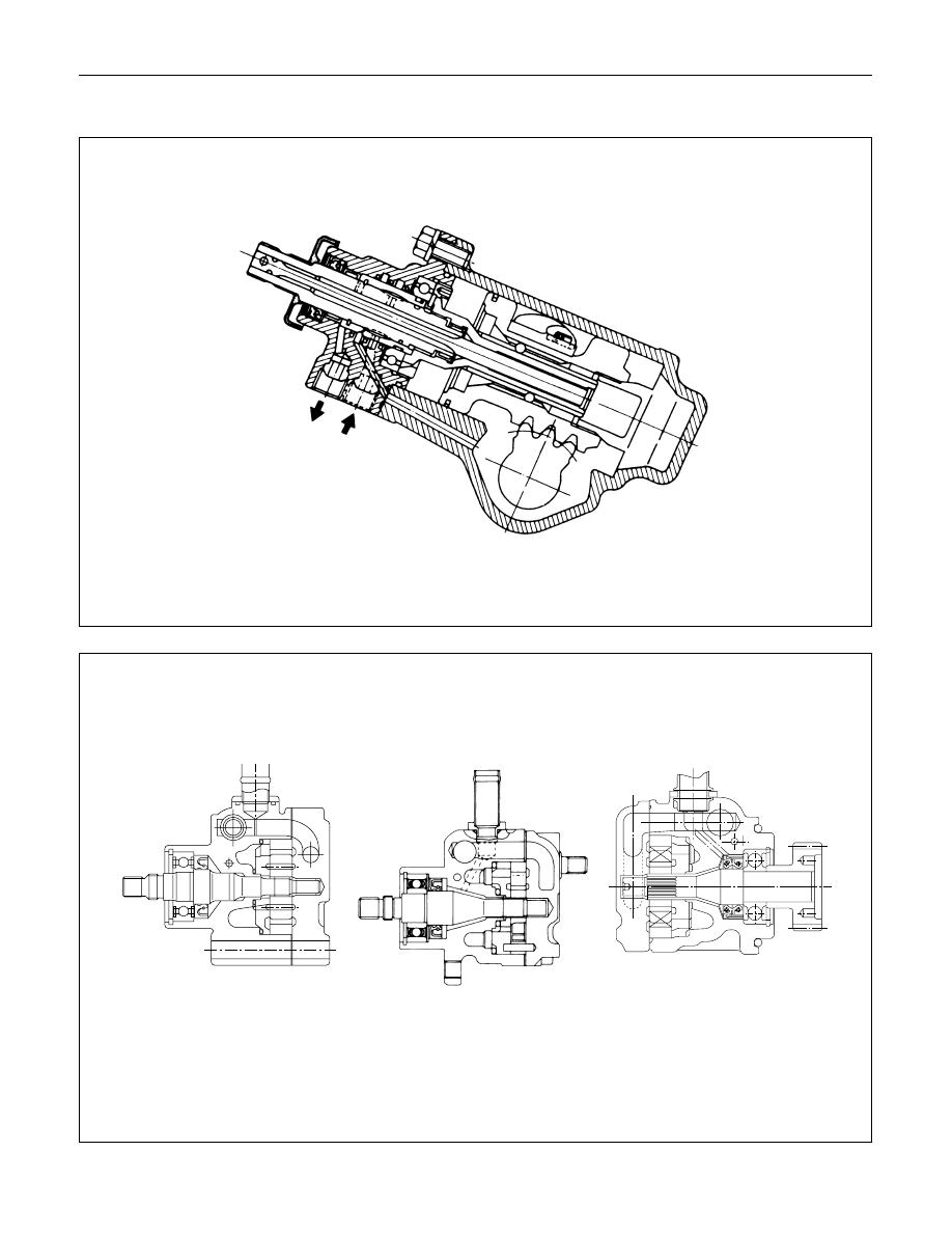
GENERAL DESCRIPTION
6VD1, 6VE1 Engine Models
4JG2 Engine Model
4JX1 Engine Model
This illustration is based on the LHD model.
Нет комментариевНе стесняйтесь поделиться с нами вашим ценным мнением.
Текст