Opel Frontera UBS. Service manual — part 2584
AUTOMATIC TRANSMISSION (AW30-40LE)
7A–199
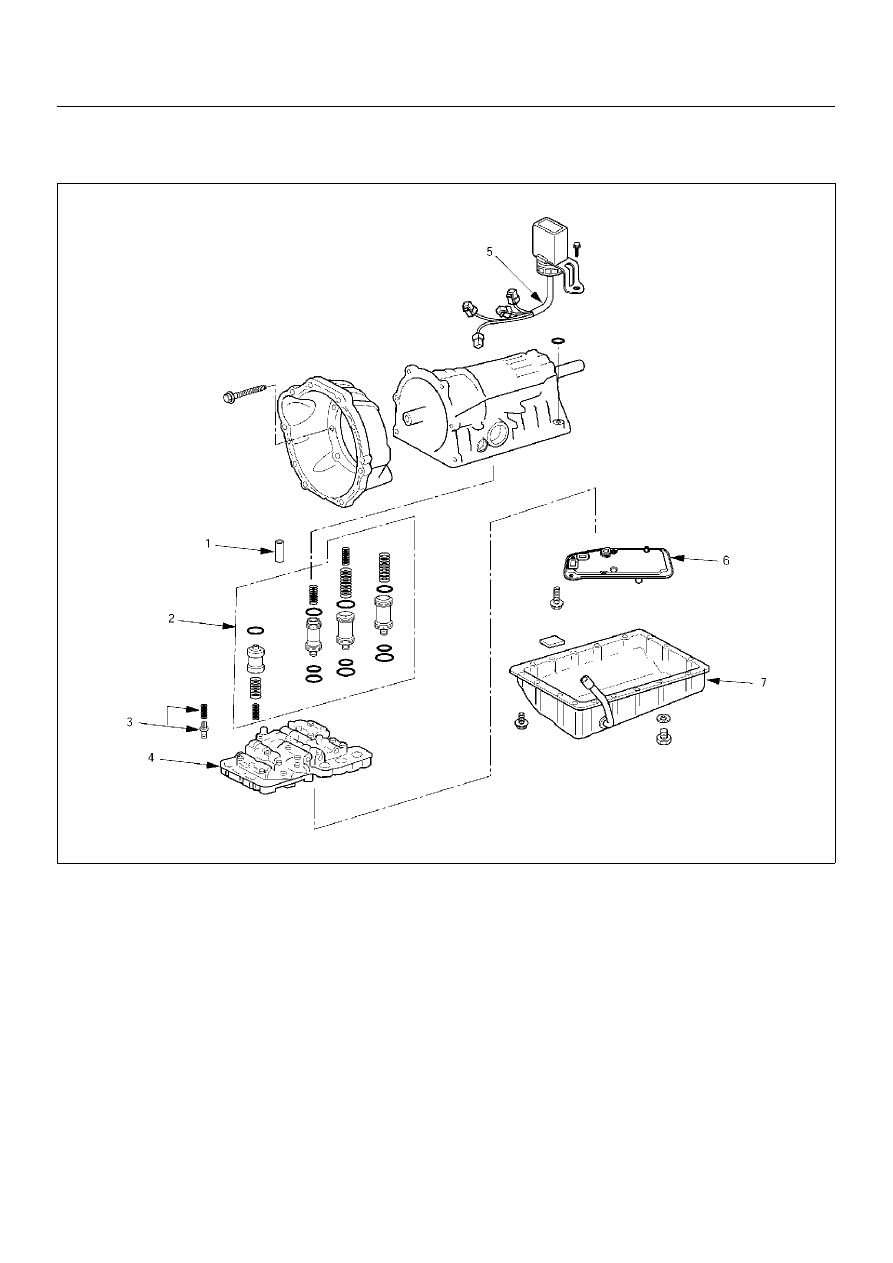
REASSEMBLY OF MAJOR COMPONENTS (2)
242RY00006
Reassembly steps
▲
1. Second brake drum gasket
▲
2. Accumulator piston
▲
3. Check valve, spring
▲
4. Valve body
▲
5. Solenoid wiring
▲
6. Oil strainer assembly
▲
7. Oil pan
7A–200
AUTOMATIC TRANSMISSION (AW30-40LE)
240RY00013
240RY00014
240RY00027
Important operations
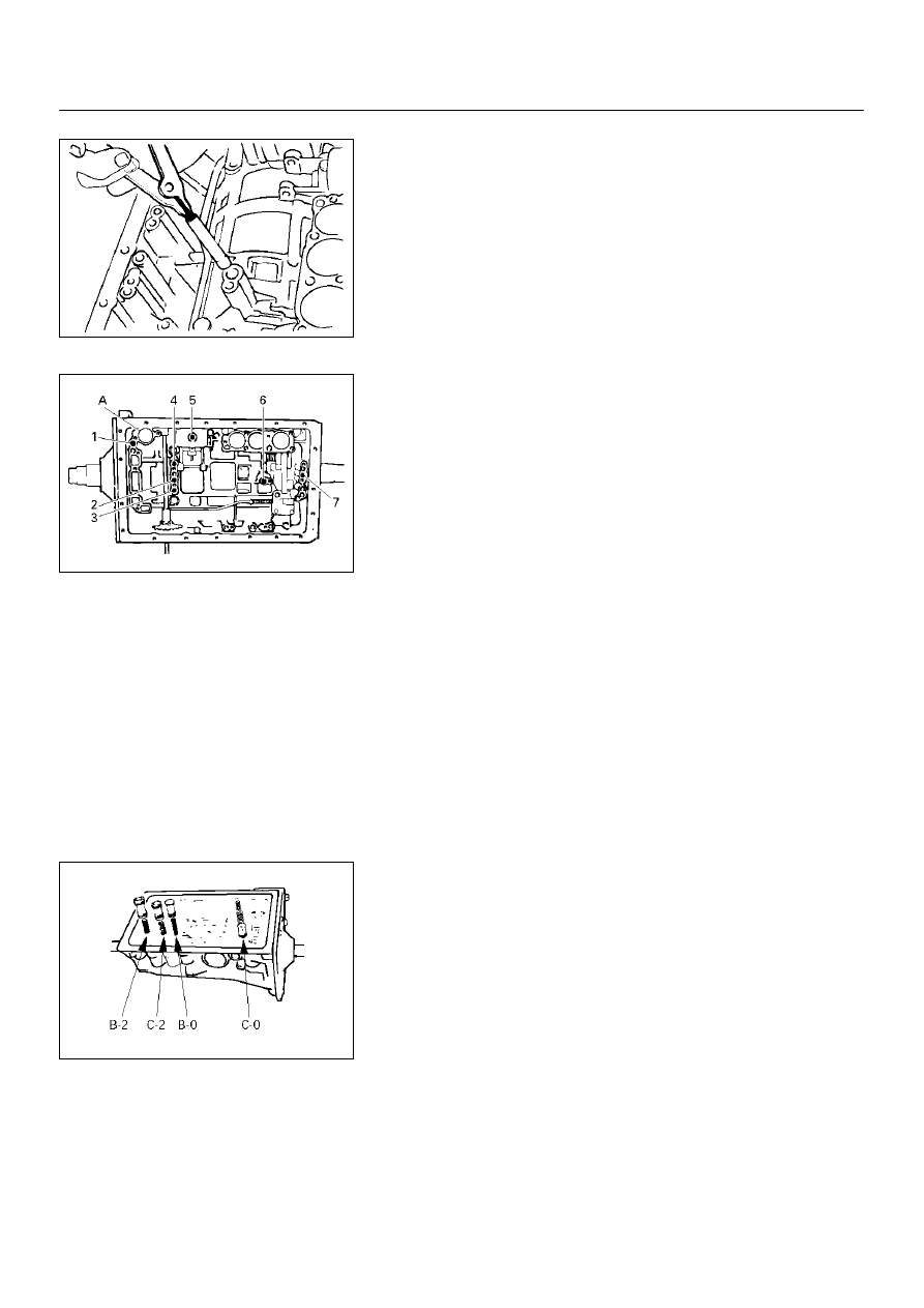
1. Second brake drum gasket
Install a new brake drum gasket to the transmission case.
Individual piston operation inspection
Check for the sound of operation while injecting
compressed air into the oil hole indicated in the figure.
NOTE:
When inspecting the direct clutch, check with the C–0
accumulator piston hole closed. If there is no noise,
disassemble and check the condition of the parts.
A : C–0 Accumulator piston hole
2. Accumulator piston
Coat the O–ring with ATF and install it to the piston.
Install the five springs and four accumulator pistons to the
bore as shown in the figure.
1: OD direct clutch
5: Second coast brake
2: Direct clutch
6. Second brake
3: Forward clutch
7. First and reverse brake
4: OD brake
AUTOMATIC TRANSMISSION (AW30-40LE)
7A–201
240RY00015
240RY00029
240RY00010
240RY00016
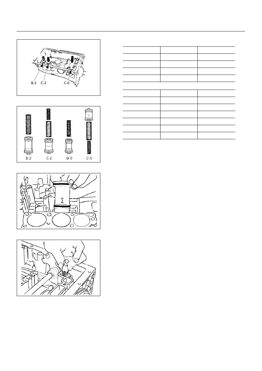
3. Check valve, spring
Install new check valve and spring.
mm (in.)
Piston
Outer diameter
Height
B–2
36.8 (1.449)
62.5 (2.461)
C–2
36.8 (1.449)
56.6 (2.228)
B–0
31.8 (1.252)
52.0 (2.047)
C–0
29.8 (1.173)
44.0 (1.732)
Spring
Free length
Outer diameter
(1) B–2
75.8 (2.984)
20.1 (0.791)
(2) C–2 (Inner)
42.1 (1.658)
14.7 (0.579)
(3) C–2 (Outer)
64.0 (2.520)
20.2 (0.795)
(4) B–0
63.6 (2.504)
16.0 (0.630)
(5) C–0(Outer)
74.6 (2.937)
20.9 (0.823)
(6) C–0(Inner)
46.0 (1.811)
14.0 (0.551)
7A–202
AUTOMATIC TRANSMISSION (AW30-40LE)
240RY00017
244RY00017
249RY00011
249RY00012
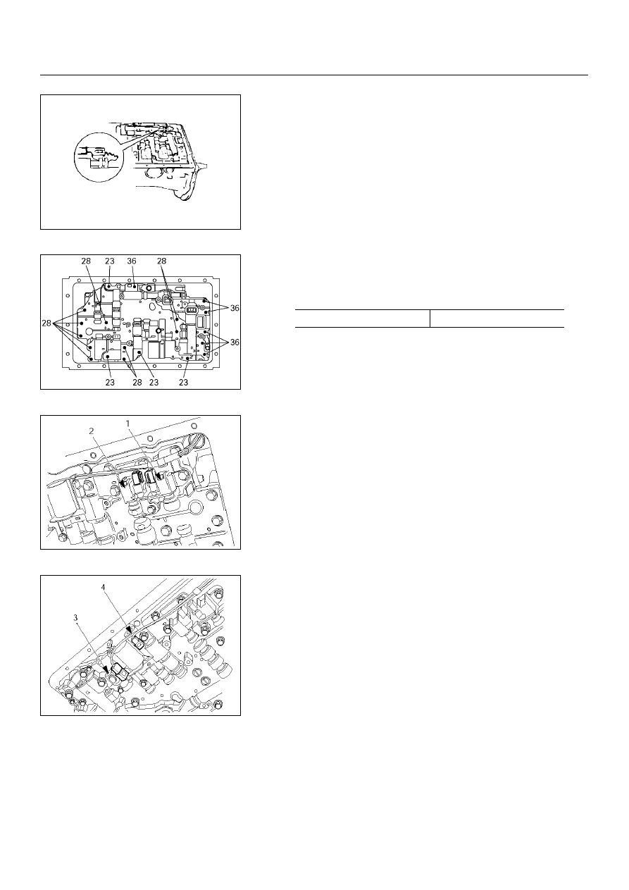
4. Valve body
Align the groove of the manual valve to the pin of the lever.
Install the twenty bolts.
Each bolt length (mm) is indicated in the figure.
5. Solenoid wiring
Coat a new O–ring with ATF, and install it to the solenoid
wiring.
Insert the solenoid wiring to the case and install the stopper
plate.
Connect the connectors to the solenoid S1(1), S2(2), lock-
up solenoid (3), and pressure control solenoid (4).
N·m (kg·m/lb·in)
Torque
10 (1.0/87)
Нет комментариевНе стесняйтесь поделиться с нами вашим ценным мнением.
Текст