Opel Frontera UBS. Service manual — part 1107
POWER ASSISTED BRAKE SYSTEM 5C – 33
2. Check the rear wheel cylinder fluid pressure.
Install the pressure gauge on bleeder screws on
the front and rear brakes.
a. Depress the brake pedal slowly until the front
wheel cylinder fluid pressure reaches 7845 kPa
(80 kg/cm
2
/ 114 psi)
Note:
• The brake pedal should be depressed
gradually until specified pressure is reached
without pumping or adjusting foot pressure.
• If the front wheel cylinder fluid pressure rises
abobe 7845 kPa (80 kg/cm
2
/ 114 psi), release
the pedal fully, then depress the pedal again.
b. Hold the front wheel cylinder fluid pressure at
7845 kPa (80 kg/cm
2
/ 114 psi) for 2 seconds,
check the rear wheel cylinder fluid pressure.
Rear wheel cylinder
fluid pressure
kPa (kg/cm
2
/ psi)
6374±539 (65±5.5 / 924±78)
c. If the rear wheel cylinder fluid pressure is not
within the specified range, adjust the fluid
pressure.
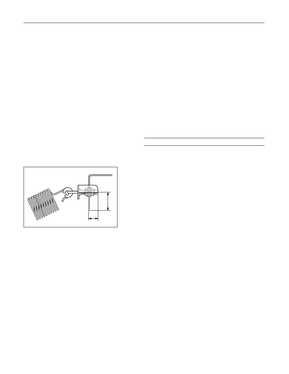
3. Adjust the rear wheel cylinder fluid pressure.
The fluid pressure can be adjusted by the bolt
projection (1) or bolt projection (2).
a. If the fluid pressure is lower than specified
range, increase the dimention (1) or (2).
b. If the fluid pressure is higher than the specified
range, decrease the dimention (1) or (2).
Reference:
Dimention (1): The fluid pressure can be
adjusted about 196 kPa (2
kg/cm
2
/ 28 psi) by one turning
of the nut.
Dimention (2): The fluid pressure can be
adjusted about 98 kPa (1 kg/cm
2
/ 14 psi) by sliding the bolt
position (per 1 mm / 0.039 in).
4. Check the rear wheel cylinder fluid pressure.
If the rear wheel cylinder fluid pressure is not
within the specified range, try the adjustment
again.
5. Bleed the brake hydraulic line and check the fluid
leak.
2
1
C05RW023
5C – 34 POWER ASSISTED BRAKE SYSTEM
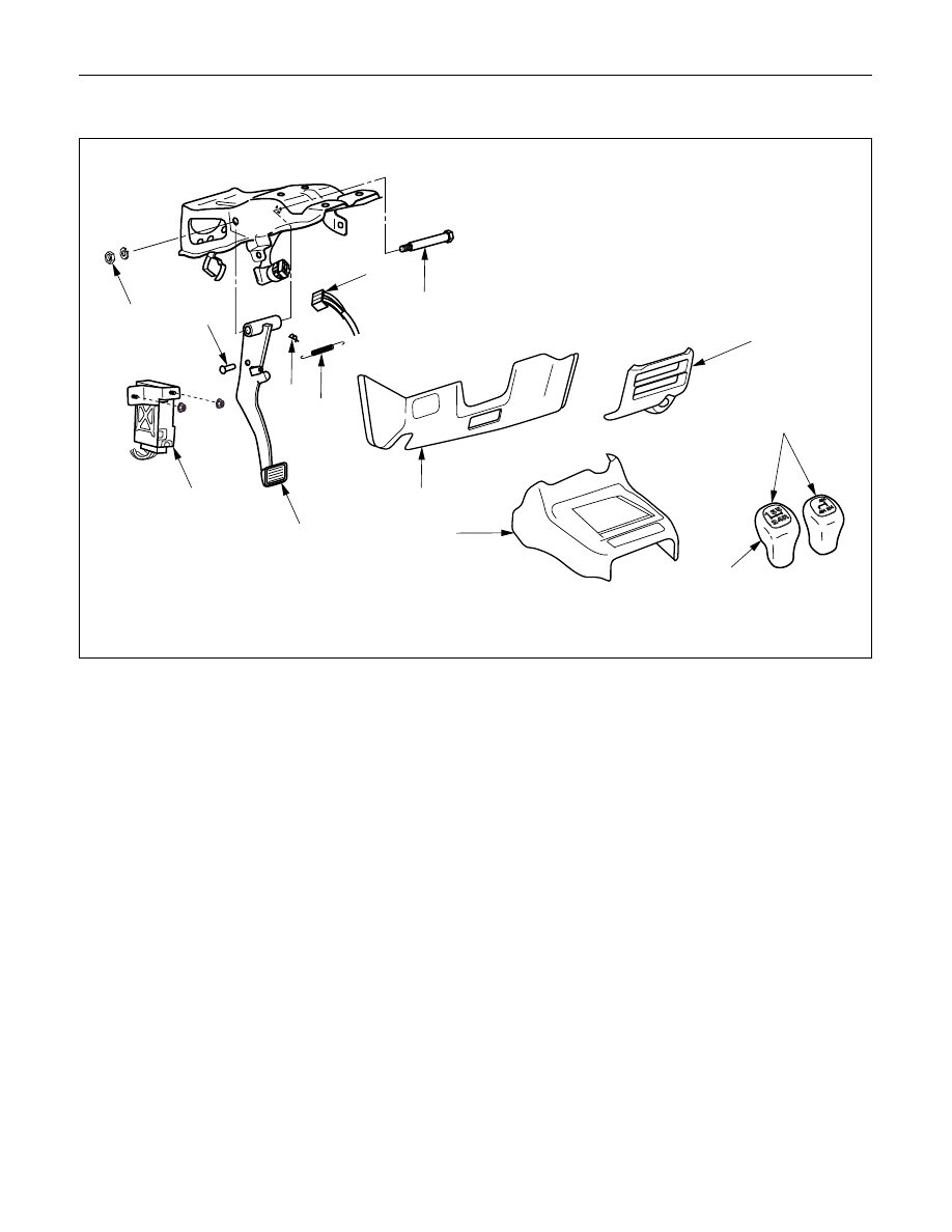
BRAKE PEDAL REPLACEMENT
10
9
5
12
4
2
7
8
6
11
3
1
M/T
Removal Steps
1.
Shift knob
2.
Front console assembly
3.
Lower cluster assembly
4.
Instrument panel driver lower cover
assembly
5.
Anti-theft controller
6.
Stoplight switch connector
7.
Return spring
8.
Snap pin
9.
Pin
10. Nut
11. Pin, fulcrum
12. Brake pedal
Installation Steps
12. Brake pedal
11. Pin, fulcrum
10. Nut
9.
Pin
8.
Snap pin
7.
Return spring
6.
Stoplight switch connector
5.
Anti-theft controller
4.
Instrument panel driver lower cover
assembly
3.
Lower cluster assembly
2.
Front console assembly
1.
Shift knob
This illustration is based on the LHD model.
POWER ASSISTED BRAKE SYSTEM 5C – 35
REMOVAL
1. Shift Knob
2. Front Console Assembly
3. Lower Cluster Assembly
4. Instrument Panel Driver Lower Cover Assembly
5. Anti-theft Controller
6. Stoplight switch Connector
7. Return Spring
8. Snap Pin
9. Pin
10. Nut
11. Pin, Fulcrum
12. Brake Pedal
INSTALLATION
12. Brake Pedal
11. Pin, Fulcrum
•
Apply grease to the entire circumference of the
fulcrum pin.
10. Nut
Bolt and Nut Torque
N·m (kg·m / lb·ft)
33 (3.3 / 24)
9. Pin
•
Apply grease to the entire circumference of the
push rod pin.
8. Snap Pin
•
Adjust pedal free travel. Refer to “Brake Pedal
Adjustment” previously in this section.
7. Return Spring
6. Stoplight Switch Connector
5. Anti-theft Connector
4. Instrument Panel Driver Lower Cover Assembly
3. Lower Cluster Assembly
2. Front Console Assembly
1. Shift Knob
5C – 36 POWER ASSISTED BRAKE SYSTEM
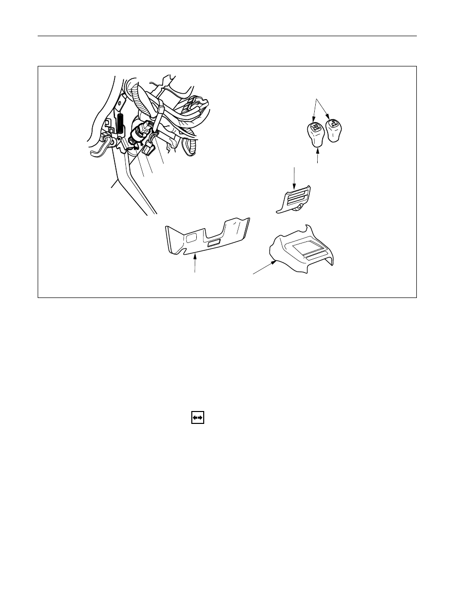
STOPLIGHT SWITCH REPLACEMENT
6
7
5
4
2
3
M/T
1
Removal Steps
1.
Shift Knob
2.
Front Console Assembly
3.
Lower Cluster Assembly
4.
Instrument Panel Driver Lower Cover
Assembly
5.
Stoplight Switch Connector
6.
Lock Nut
7.
Switch
Installation Steps
7.
Switch
6.
Lock Nut
5.
Stoplight Switch Connector
4.
Instrument Panel Driver Lower Cover
Assembly
3.
Lower Cluster Assembly
2.
Front Console Assembly
1.
Shift Knob
REMOVAL
1. Shift Knob
2. Front Console Assembly
3. Lower Cluster Assembly
4. Instrument Panel Driver Lower Cover Assembly
5. Stoplight Switch Connector
6. Lock Nut
7. Switch
This illustration is based on the LHD model.
Нет комментариевНе стесняйтесь поделиться с нами вашим ценным мнением.
Текст