Opel Frontera UBS. Service manual — part 1308
CHARGING SYSTEM 6D3 – 9
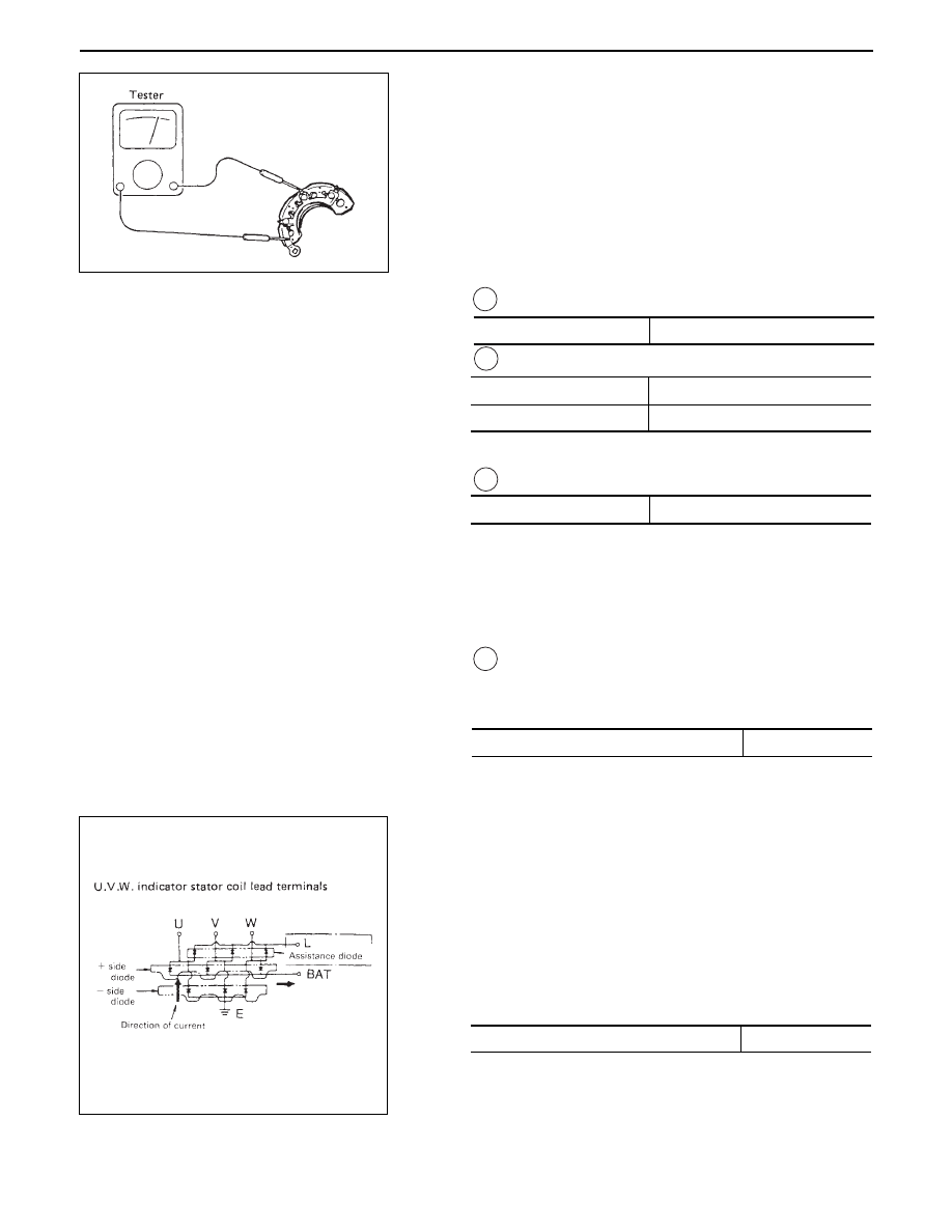
IC REGULATOR
Measureing instruments is necessary.
Take the following measurements with the
instruments connected as shown in the illustration.
•
V1 Voltage at BAT1
•
V2 Voltage across F–E
•
Take measurement with ‘S’ terminal disconnected.
•
V3 Measure the voltage at BAT1 – BAT2.
•
Measurement the voltage across the E–F while
varying resistance gradually from zero using variable
resistor.
Then check that voltage increases from 2V to 10 – 13.
If increase in voltage is interrupted at any point,
replace the regulator.
•
V4 Measure the voltage across the intermediate tap
on variable resistor and ‘E’ terminal without actuating
the variable resistor.
If measured value deviates from the standard, replace the
regualator.
Check the following with the instrument connected as
illustrated.
Measure the voltage across the teminals B and E by
gradually increasing voltage with variable resistor RV.
Check to see if voltage increases from lower than 2V to
range from 10 to 13 volts.
If the voltage does not vary, the regulator is defective and
should be replaced.
Check the voltage across the intermediate tap of the
variable resistor and terminal E without actuating the
variable resistor.
If measured voltage deviates from the standard value,
replace the regulator.
Standard
10 – 13
V
Standard
Limit
2 or less
2 or more
V
Standard
20 – 26
V
Standard voltage at 20°C (68°F)
14.0 – 14.6
V
Standard voltage at 20°C (68°F)
14.5 – 16.6
V
6D3 – 10 CHARGING SYSTEM
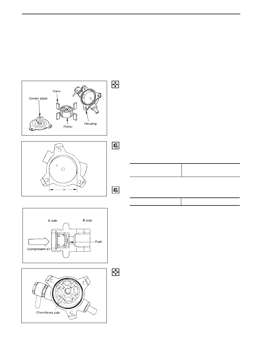
VACUUM PUMP
Visual check
•
Inspect the following parts for wear, damage or other
abnormal conditions.
Standard
60.0 – 60.1
(2.362 – 2.366)
mm (in)
Vane
Measure the length of vanes
Standard
14.2– 15.2(0.559–0.598)
mm (in)
Check valve
1.
Apply a light pressure onto the ”B” side of valve with
a screw driver and check that valve operates
smoothly.
2.
Apply compressed air onto ”A” side of valve and
check if there is air leak.
Housing
•
Measure the inside diameter of housing and place if it
exceed the standard.
Reassembly of vacuum pump
1.
Position the rotor, with the serrated boss turned up,
on the center plate and housing.
Align the holes in center plate and rotor.
2.
Install vanes into slits in rotor.
The vanes should be installed with chamfered side
turned outward.
3. Install the O-ring and center plate
Disassembly of Vacuum pump
•
For the center plate, rotor and vane in the mentioned.
CHARGING SYSTEM 6D3 – 11
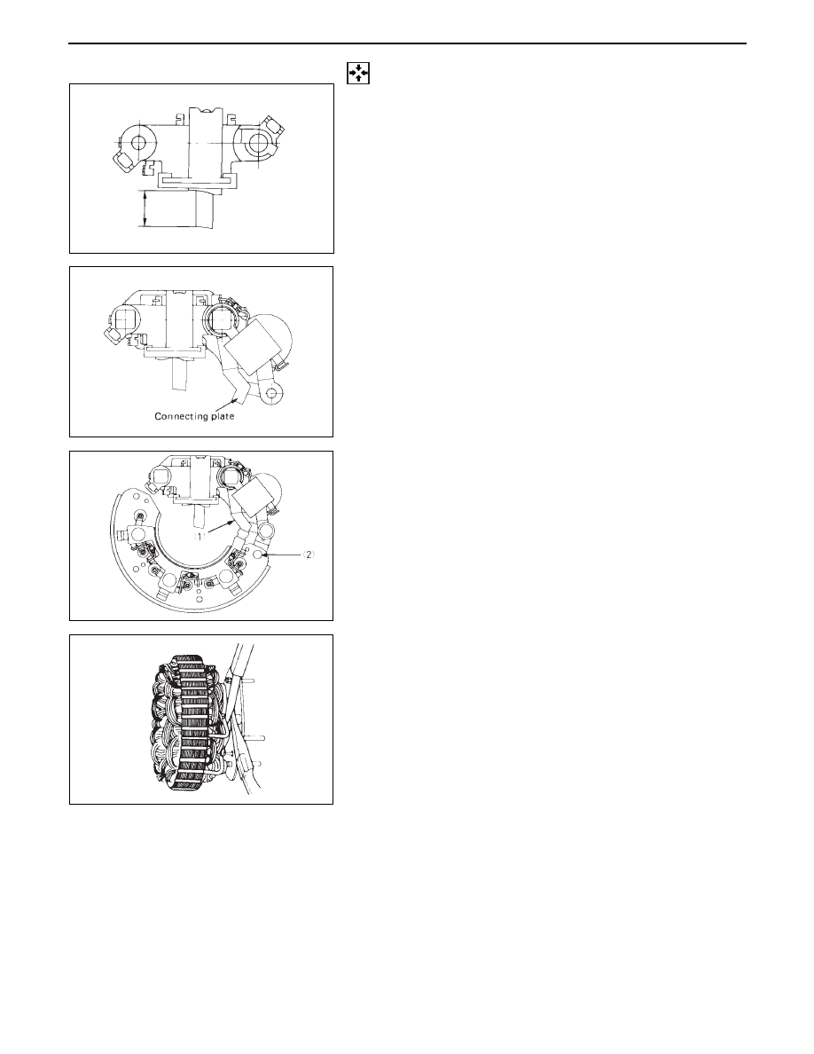
REASSEMBLY
17. Brush Holder
16. IC Regulator Assembly
•
Hold the brush in the holder as shown in the
illustration and solder the lead wire.
•
Put the IC regulator on the brush holder and
press the bolt.
Bushing and connecting plate must be installed
when pressing the bolt.
15. Diode
•
Connect the terminals by fixing the rivet at ➀
and soldering the terminal at ➁ .
14. Stator
•
When connecting stator coil leads and diode
leads using solder, use long-nose pliers and
finish the work as quickly as possible to prevent
the heat from being transferred to the diodes.
13. Rear Cover
12. Terminal Bolt and Nut
11. Rear Bearing
10. Front Bearing
9. Bearing Retainer
8. Front Cover Assembly
7. Spacer
6. Rotor
5. Fan
4. Pulley
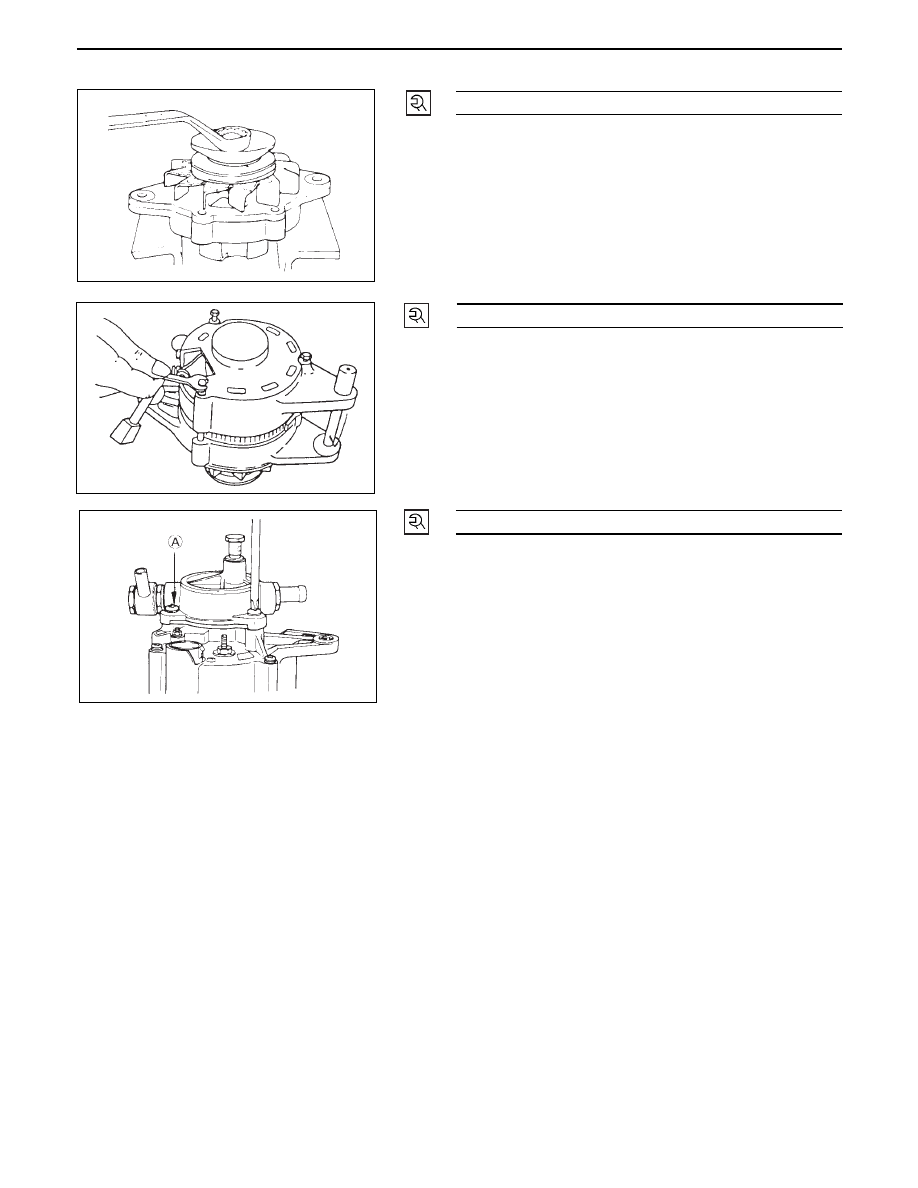
3. Pulley Nut
•
Cover vice with copper plates, clamp the rotor
with the vice, and tighten nut to the specified
torque.
2. Through Bolt
•
Place guide bar through the holes in front cover
and rear cover flange for alignment, then install
the through bolts.
1. Vacuum Pump
•
Install and mount the housing to the generator
using 3 bolts.
•
Pour engine oil (5 cc or so) in through the filler
port, then check that generator pulley can be
turned smoothly with hand.
6D3 – 12 CHARGING SYSTEM
52 (5.3 / 38)
N·m (Kg·m/lb·ft)
7 (0.7 / 61)
N·m (Kg·m/lb·in)
7 (0.7 / 61)
N·m (Kg·m/lb·in)
Нет комментариевНе стесняйтесь поделиться с нами вашим ценным мнением.
Текст