Opel Frontera UBS. Service manual — part 1307
CHARGING SYSTEM 6D3 – 5
UNIT REPAIR
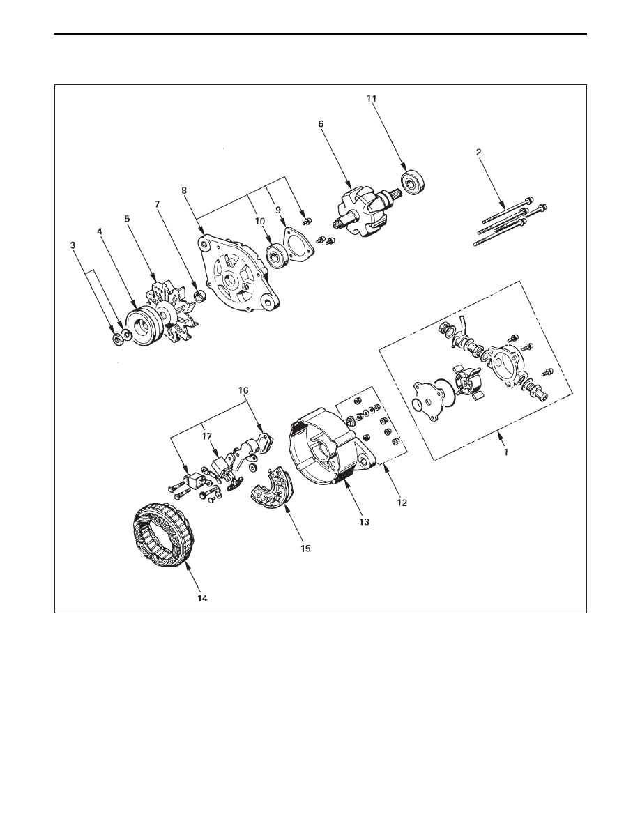
Disassembly Steps
1. Vacuum pump
2. Through bolt
3. Pulley nut
4. Pulley
5. Fan
6. Rotor
7. Spacer
8. Front cover assembly
9. Bearing retainer
10. Front bearing
11. Rear bearing
12. Terminal bolt and nut
13. Rear cover
14. Stator
15. Diode
16. IC regulator assembly
17. Brush holder
Reassembly Steps
To reassemble, follow the disassembly steps in the
reverse order.
6D3 – 6 CHARGING SYSTEM
DISASSEMBLY
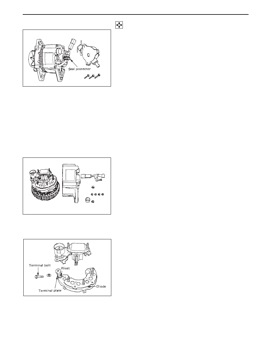
1.
Vaccum Pump
•
Dram fluid from discharged port.
•
Remove the vacuum pump fixing bolts. Hold the
center plate and remove the vacuum pump
horizontally in direction in line with the rotor
shaft.
2. Through Bolt
3. Pulley Nut
•
Cover the vice with copper plates, clamp the rotor
with vice, and remove the nut.
4. Pulley
5. Fan
6. Rotor
7. Spacer
8. Front Cover Assembly
9. Bearing Retainer
10. Front Bearing
11. Rear Bearing
12. Terminal Bolt and Nut
13. Rear Cover
•
Remove the nuts fixing the B terminal and diode
holder.
Separate the stator and rear cover.
Note the position of insulation washers to ensure
reassembly into original position.
14. Stator
15. Diode
•
Separate the diodes from the stator by melting
away solder on stator coil and diode.
When melting solder, hold the lead wire with
longnose pliers to prevent heat from being
transferred to the diodes.
16. IC Regulator
•
•
Separate the IC regulator from the diode by
melting away solder on IC regulator holder plate
and removing the nut.
CHARGING SYSTEM 6D3 – 7
17. Brush Holder Assembly
•
Remove the serrated bolts and melt away solder on
IC regulator.
•
Do not remove the serrated bolts unless the
replacement of brush or condenser.
To install, follow the removal steps in the reverse
order.
INSPECTION AND REPAIR
Repair or replace necessary parts if extreme wear or
damage is found during inspection.
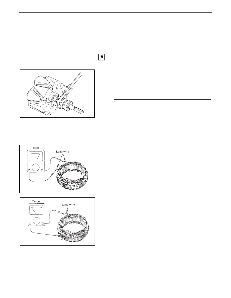
ROTOR ASSEMBLY
1. Check the rotor slip ring surfaces for contamination and
roughness. If rough, polish with #500-600 sandpaper.
2. Measure the slip ring diameter, and replace if it exceeds
the limit.
3.
Check for continuity between slip reings, and replace if
there is no continuity.
4.
Check for continuity between slip ring and rotor core or
slip ring and rotor shaft.
In case of continuity, replace the rotor assembly.
STATOR COIL
1.
Check for continuity between respective phases.
In case of no continuity, replace the stator.
2.
Check for continuity across one of the stator coils and
stator core. If a continuity exists, replace the coil.
34.6(1.36)
33.6(1.32)
mm (in)
Standard
Limit
6D3 – 8 CHARGING SYSTEM
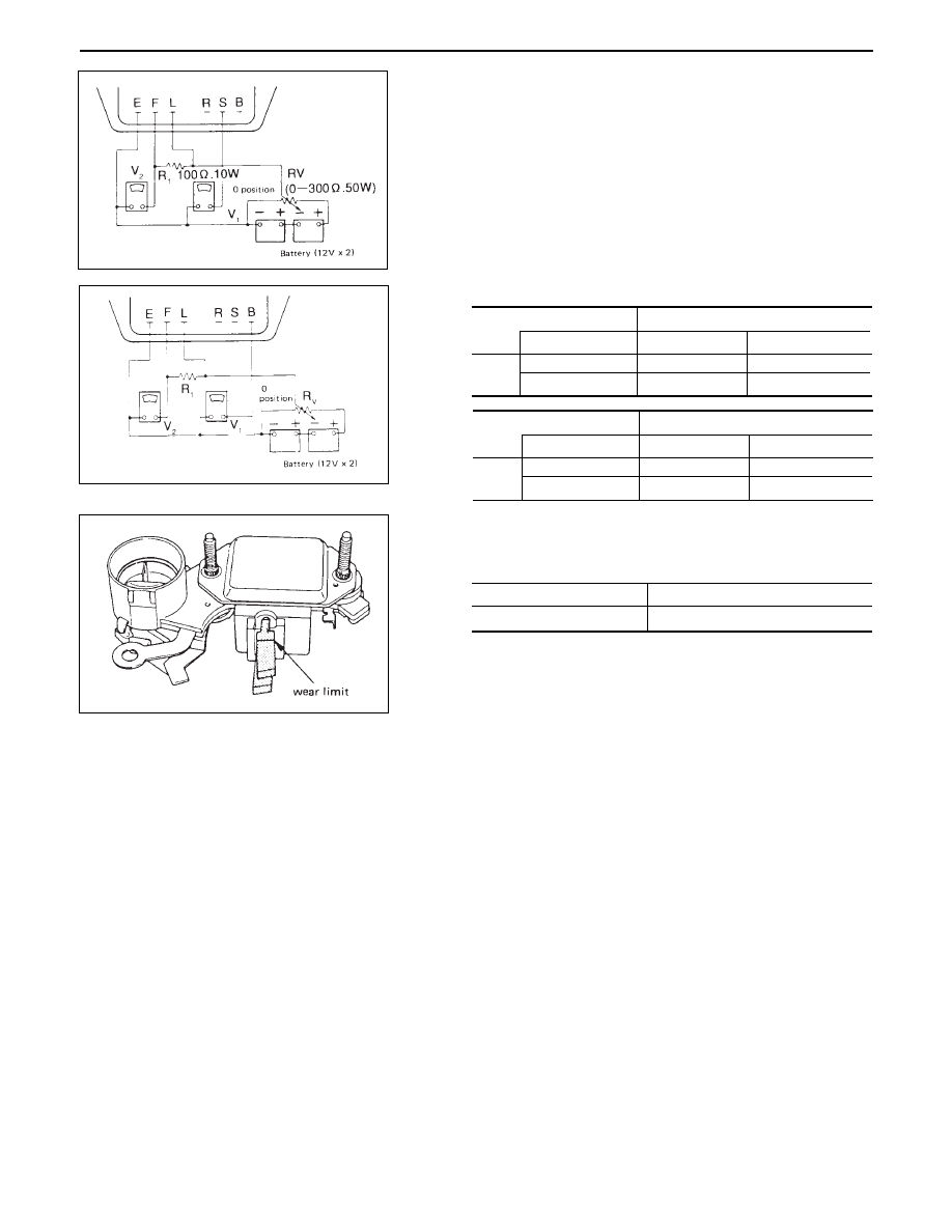
DIODE
1.
Check for continuity across the terminal (example:
across BAT and U). If a continuity exists, the diode is
in satisfactory condition. If no continuity exists the
diode is defective.
2.
Make a test with the polarities reversed. If no
continuity exists, the diode is in satisfactory
condition. If a continuity exists at any point, the
diode is defective and should be replaced.
Auxiliary diodes are not provided with the terminal
and continuity test should be made across the
terminals of the conventional diodes.
BRUSH
Measure length of brushes.
Brush length (L)
Across terminals
BAT (Positive side (+) diodes)
Tester pin
Positive side
Negative side
Positive side
Continuity
Negative side
No continuity
U.V.W.
Across terminals
BAT (Positive side (+) diodes)
Tester pin
Positive side
Negative side
Positive side
Continuity
Negative side
No continuity
U.V.W.
20(0.7)
6 (0.24)
mm(in)
Standard
Limit
Brushes are provided with a line which indicates the
limit of usage.
Нет комментариевНе стесняйтесь поделиться с нами вашим ценным мнением.
Текст