Opel Frontera UBS. Service manual — part 2241
6D3–21
STARTING AND CHARGING SYSTEM
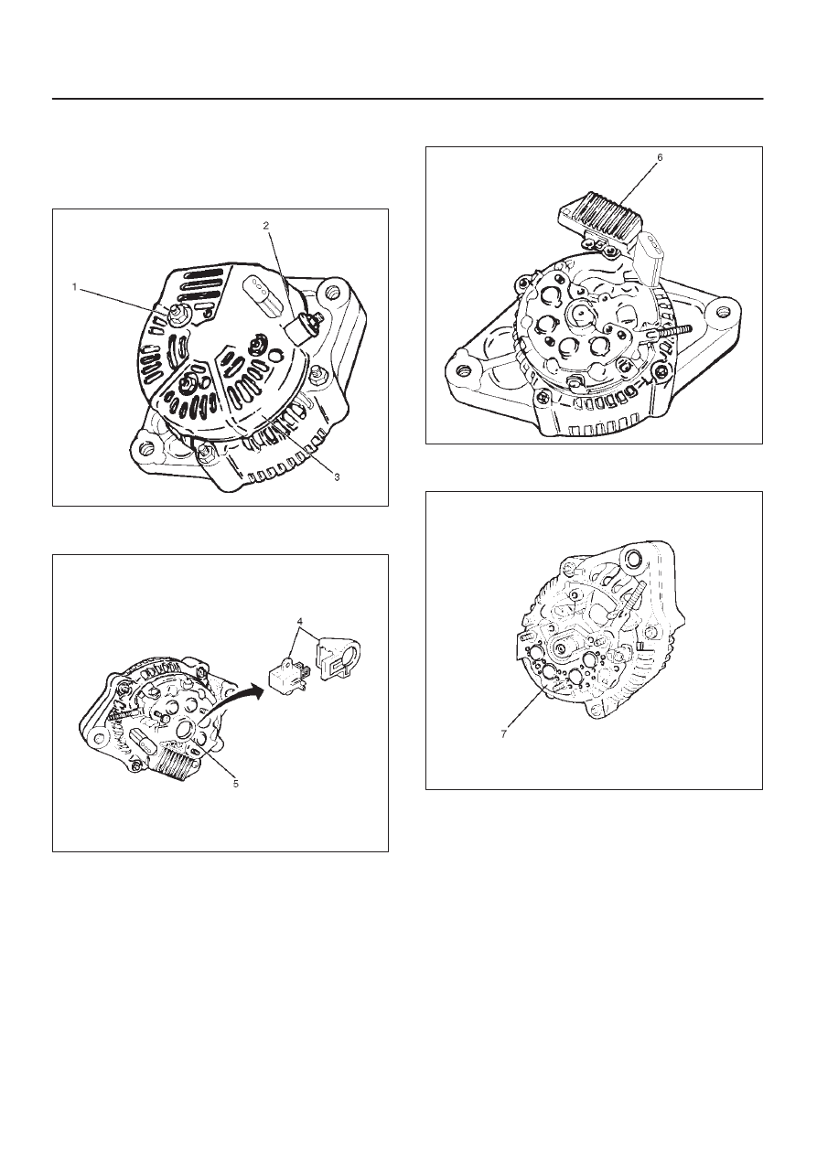
Disassembly
1. Terminal insulator and nut(2).
2. Remove three nuts(1) on the rear cover and a nut on
terminal B and insulator, then remove the rear
cover(3).
060RW005
3. Remove two screws that fix the brush holder(5) and
rectifier, then remove the brush holder assembly(4).
060RW004
4. Remove three screws on the IC regulator, then the IC
regulator assembly(6).
060RW003
5. Remove four screws that fix rectifier(7) and stator
lead wires.
066RW004
6D3–22 STARTING AND CHARGING SYSTEM
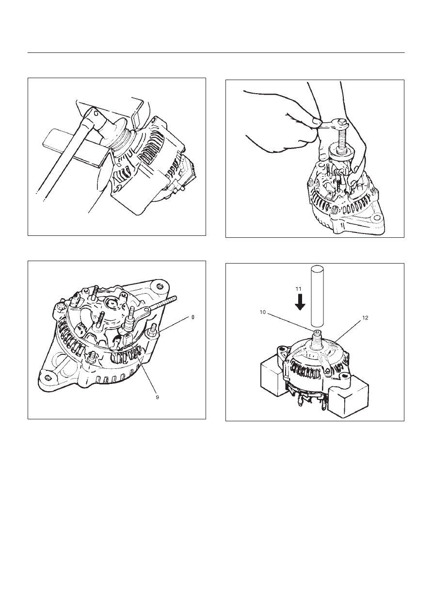
6. Secure the pulley directly in the vise between two
copper plates, and remove the nut and pulley.
066RS010
7. Remove four nuts(8) that secure the front cover
assembly and rear end cover, and an insulator(9).
066RW005
8. Use the puller to remove the rear end cover.
9. Rotor assembly
066RS012
10. Pull the rotor assembly(10) off the front cover
assembly(12) using a bench press(11).
066RW006
6D3–23
STARTING AND CHARGING SYSTEM
Inspection and Repair
Repair or replace necessary parts if extreme wear or
damage is found during inspection.
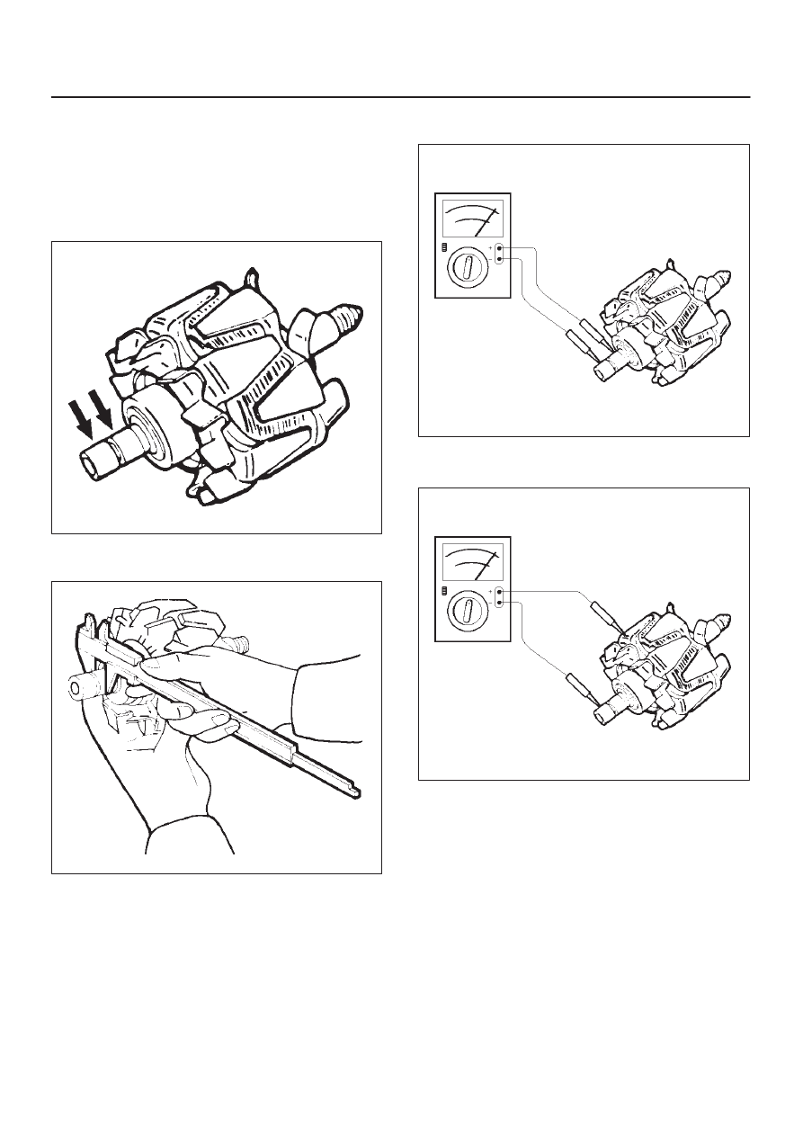
Rotor Assembly
1. Check the rotor slip ring surfaces for contamination
and roughness. If rough, polish with #500—600
sandpaper.
066RS014
2. Measure the slip ring diameter, and replace if it
exceeds the limit.
066RS015
3. Check resistance between slip rings, and replace if
there is no continuity.
066RS016
4. Check for continuity between slip ring and rotor core.
In case of continuity, replace the rotor assembly.
066RS017
6D3–24 STARTING AND CHARGING SYSTEM
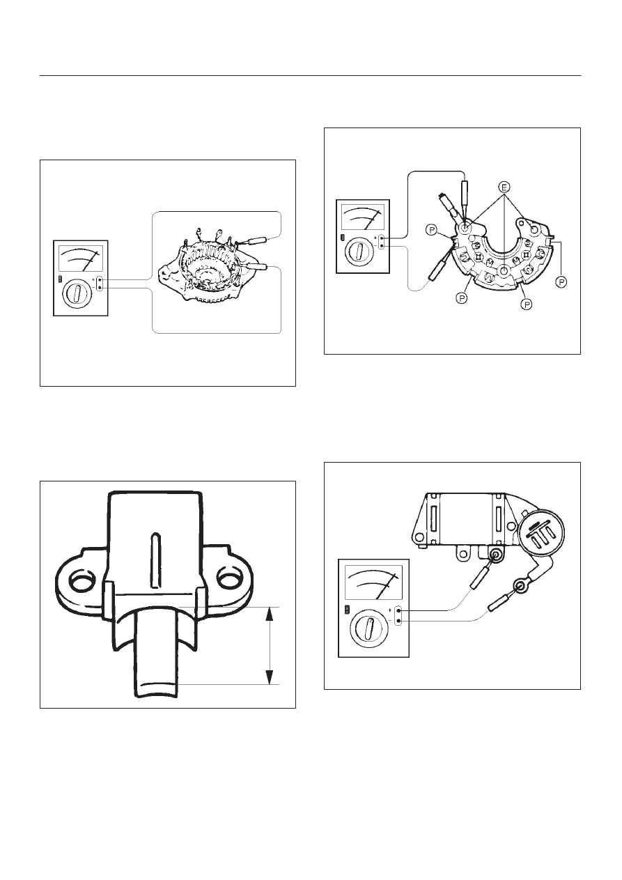
Stator Coil
1. Measure resistance between respective phases.
2. Measure insulation resistance between stator coil
and core with a mega–ohmmeter.
If less than standard, replace the coil.
066RS018
Brush
Measure the brush length.
If more than limit, replace the brush.
Standard: 10.mm (0.4134 in)
Limit: 8.4.mm (0.3307 in)
066RS019
Rectifier Assembly
Check for continuity across “P” and “E” in the
×
100W
range of multimeter.
066RW002
Change polarity, and make sure that there is continuity in
one direction, and not in the reverse direction. In case of
continuity in both directions, replace the rectifier
assembly.
IC Regulator Assembly
Check for continuity across “B” and “F” in the
×
100W
range of multimeter.
066RS021
Change polarity, and make sure that there is continuity in
one direction, and not in the reverse direction. In case of
continuity in both directions, replace the IC regulator
assembly.
Нет комментариевНе стесняйтесь поделиться с нами вашим ценным мнением.
Текст