Opel Frontera UBS. Service manual — part 463
6D – 8 ENGINE ELECTRICAL
UNIT REPAIR
8
24
1
3
23
25
2
14
15
21
22
20
19
18
17
16
10
9
11
13
12
7
6
5
4
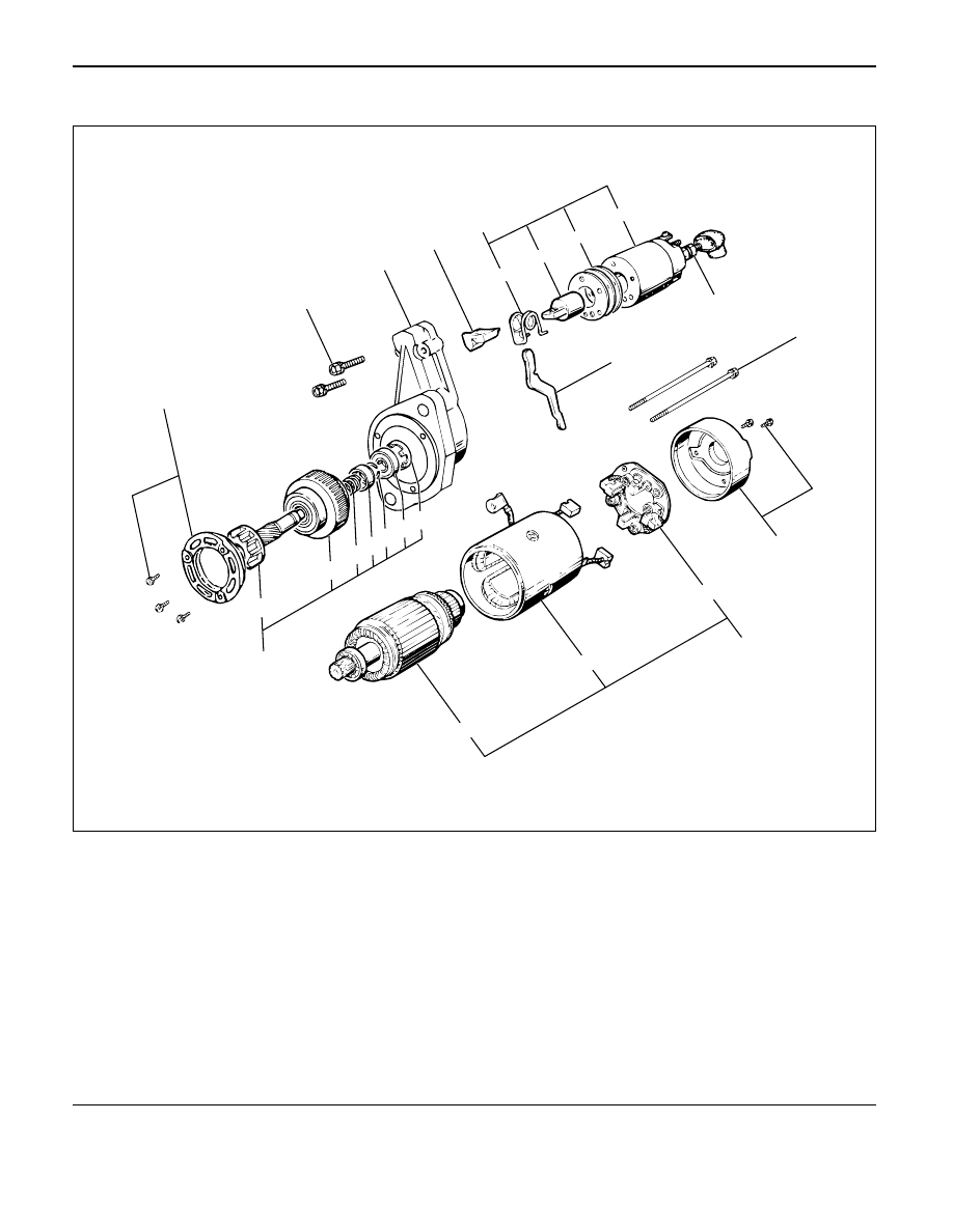
Legend
(1)
Terminal
(2)
Bolt
(3)
Magnetic Switch
(4)
Torsion Spring
(5)
Plunger
(6)
Shim
(7)
Magnetic Switch
(8)
Through Bolt
(9)
Rear Cover
(10)
Motor Assembly
(11)
Brush Holder
(12)
Armature
(13)
Yoke Assembly
(14)
Bearing Retainer
(15)
Pinion Assembly
(16)
Bearing Holder
(17)
Bearing
(18)
Clip
(19)
Stopper
(20)
Spring
(21)
Pinion Shaft
(22)
Clutch
(23)
Dust Cover
(24)
Shift Lever
(25)
Gear Case
065RW040
ENGINE ELECTRICAL 6D – 9
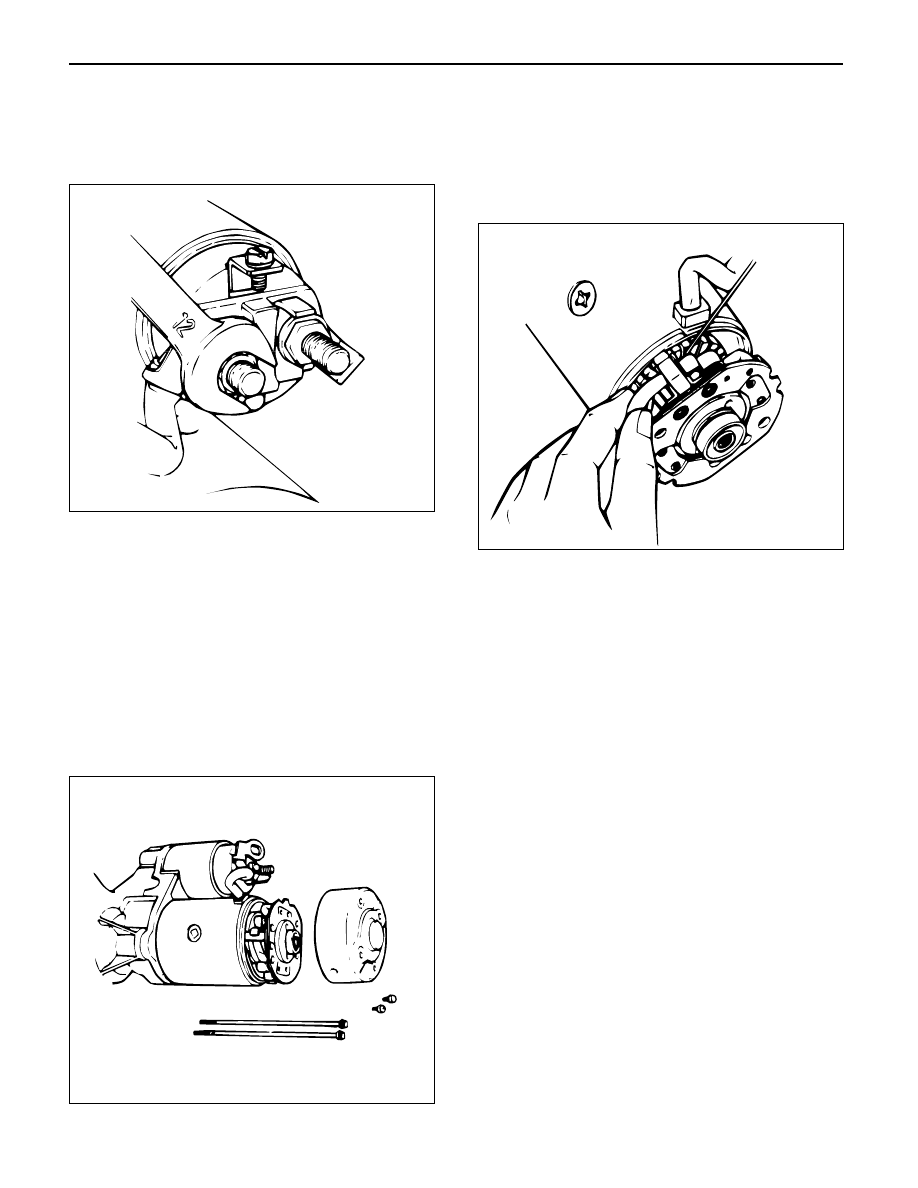
DISASSEMBLY
1. Terminal Nut
1) Loosen the nut on terminal “M” of magnetic
switch and disconnect the connector cable.
2. Bolt (2 pcs)
3. Magnetic Switch Assembly
4. Torsion Spring
1) Remove torsion spring from magnetic switch
assembly.
5. Plunger
6. Shim
7. Magnetic Switch
8. Through Bolt
9. Rear Cover
1) Remove the through bolts, then remove the rear
cover.
10. Motor Assembly
11. Brush Holder
1) Raise a brush spring to detach the negative side
of the brushes (2 pcs) from the commutator face
and remove the positive side of brushes (2 pcs)
from the positive side of brushes (2 pcs) from
the brush holder.
12. Armature
13. Yoke Assembly
14. Bearing Retainer
15. Pinion Assembly
16. Bearing Holder
17. Bearing
18. Pinion Stopper Clip
1) Remove the stopper clip using a screw driver of
equivalent size.
19. Pinion Stopper
20. Return Spring
21. Pinion Shaft
22. Clutch
23. Dust Cover
24. Shift Lever
25. Gear Case
065RW044
065RW043
065RW042
6D – 10 ENGINE ELECTRICAL
INSPECTION AND REPAIR
Repair or replace necessary parts if extreme wear or
damage is found during inspection.
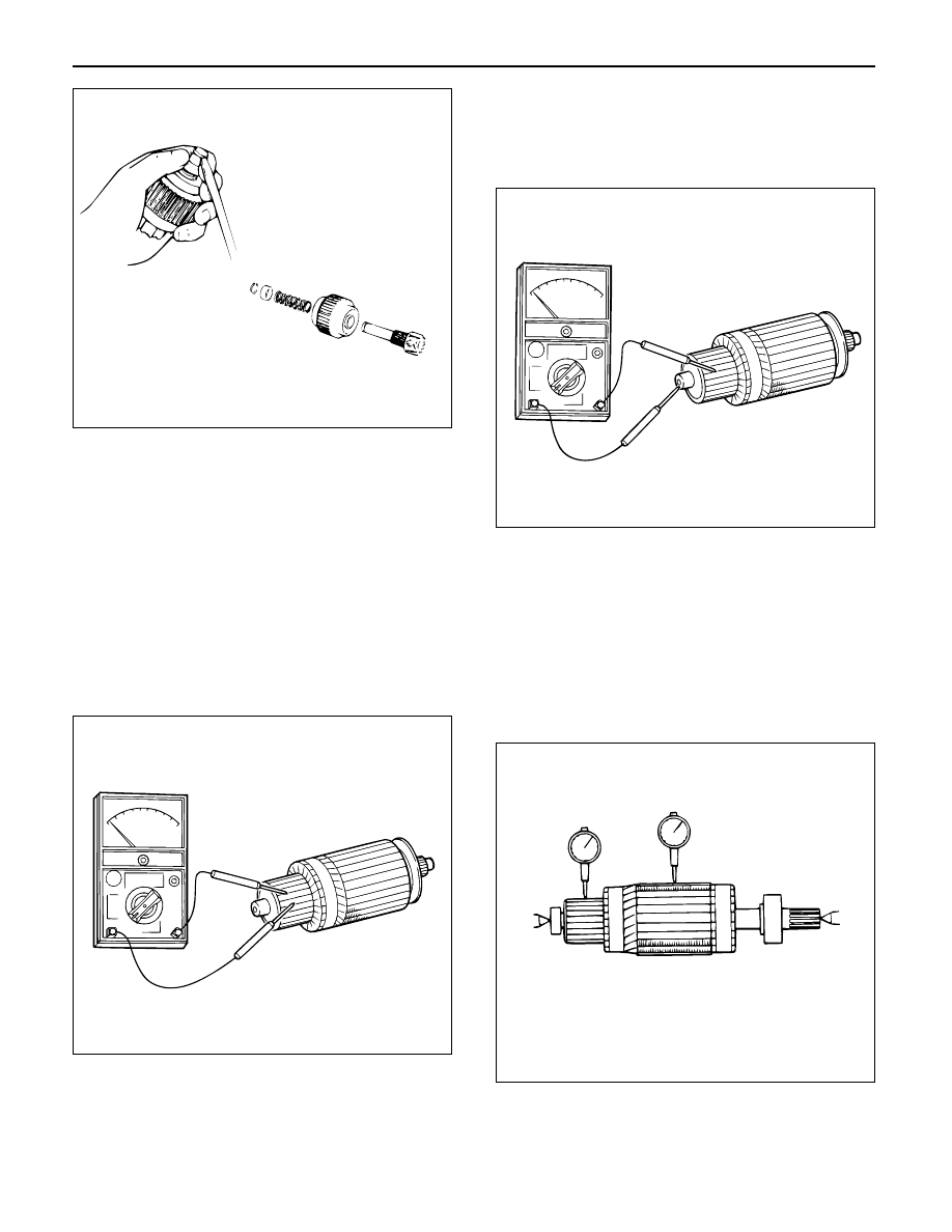
Armature
1) Measure the outer diameter of commutator, and
replace with a new one if it is out of the limit.
Standard: 38.0 mm (1.50 in)
Limit: 36.5 mm (1.44 in)
2) Check for continuity between commutator and
segments. Replace commutator if there is no
continuity (i.e., disconnected).
3) Check for continuity between commutator and
shaft. Also, check for continuity between
commutator and armature core, armature core and
shaft. Replace commutator if there is continuity
(i.e., internally grounded).
4) Measure runout of armature core and commutator
with a dial gage. Repair or replace, if it exceeds the
limit.
Armature
Standard: 0.05 mm (0.002 in) Max.
Limit: 0.1 mm (0.004 in)
Commutator
Standard: 0.05 mm (0.002 in) Max.
Limit: 0.1 mm (0.004 in)
065RW041
065RS015
065RS016
045RW045
ENGINE ELECTRICAL 6D – 11
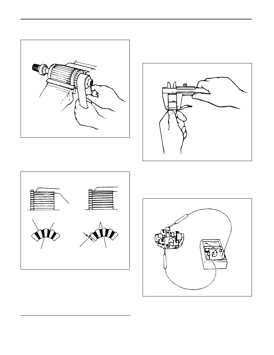
5) Polish the commutator surface with sand paper
#500 to #600 if it is rough.
6) Measure the depth of insulator in commutator.
Repair, if it is below the limit.
Standard: 0.5 – 0.8 mm (0.02 – 0.03 in)
Limit: 0.2 mm (0.008 in)
Legend
(1) Steel Saw
(2) Chamfer
(3) Correct Condition
(4) Depth of Insulator
(5) Incorrect Condition
(6) Insulator
(7) Commutator Segment
Brush
1) Measure the length of brush.
Replace with a new one, if it is below the limit.
Standard: 18.0 mm (0.71 in)
Limit: 11.0 mm (0.43 in)
Brush holder
1) Check for continuity between brush holder (+) and
base (–). Replace, if there is continuity (i.e.,
insulation is broken).
065RW105
1
6
5
3
4
2
7
065RW102
065RW103
065RW104
Нет комментариевНе стесняйтесь поделиться с нами вашим ценным мнением.
Текст