Opel Frontera UBS. Service manual — part 462
6D – 4 ENGINE ELECTRICAL
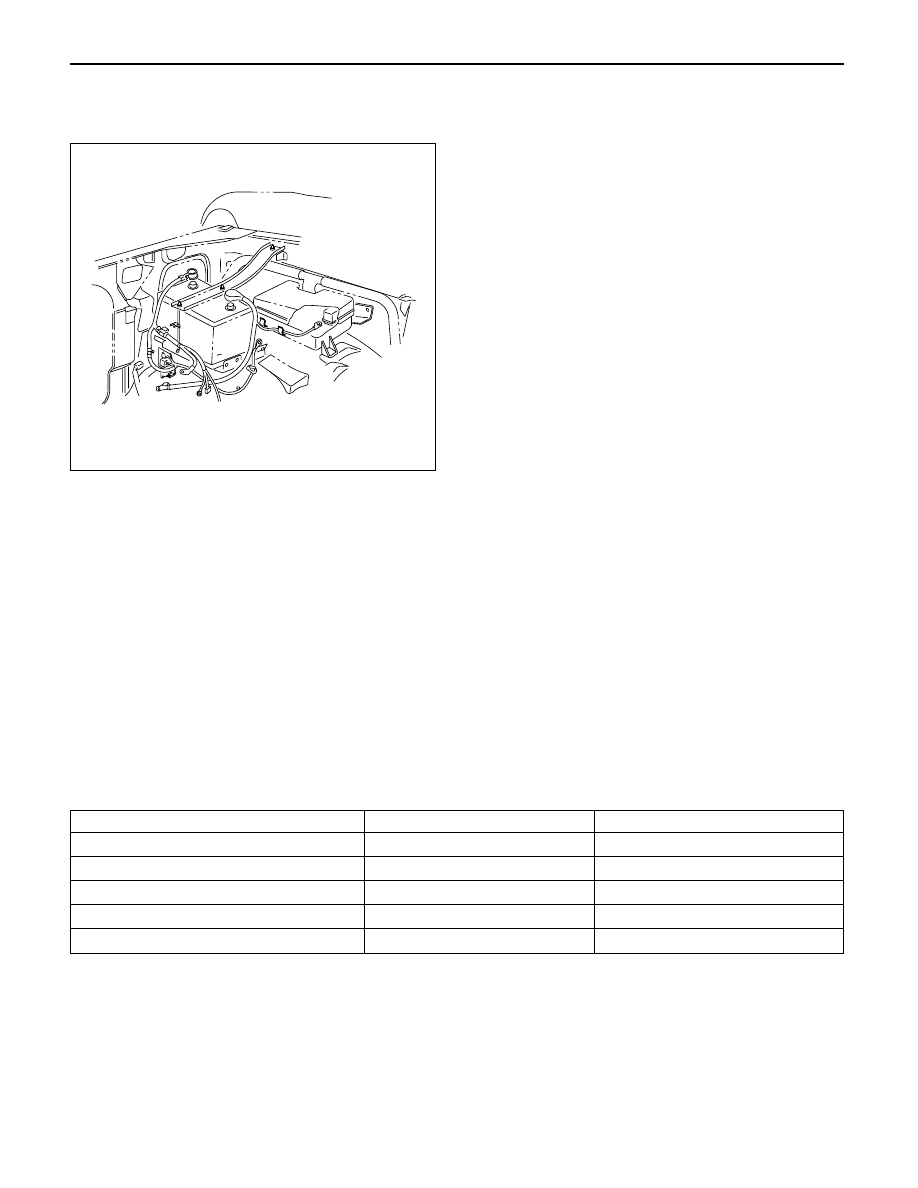
REMOVAL AND INSTALLATION OF THE
BATTERY
REMOVAL
1. Negative cable
2. Positive cable
3. Retainer screw and rods
4. Retainer
5. Battery
INSTALLATION
To install the battery, follow the removal procedure in
the reverse order, noting the following points:
1. Make sure that the rod is hooked on the body side.
065RW029
MAIN DATA AND SPECIFICATIONS
Model (JIS)
80D26R–MF
75D26R–MF
Voltage (V)
12
12
Cold-Cranking Performance (Amp)
582
490
Reserve Capacity (Min)
133
123
Load Test (Amp)
300
300
Fast Charge Maximum Amperage (Amp)
6.5
6.5
ENGINE ELECTRICAL 6D – 5
STARTING SYTEM
GENERAL DESCRIPTION
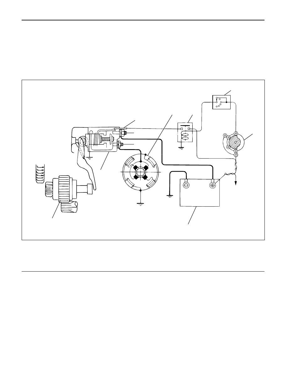
STARTING CIRCUIT
The cranking system consists of a battery, starter,
starter switch, starter relay, etc. and these main
components are connected as shown in the illustration.
“S”
“B”
“M”
Battery
5
4
3
2
IG1
ST
B2
B1
1
7
6
P
N
N
Legend
(1)
Inhibitor Switch
(2)
Starter Switch
(3)
Battery
(4)
Magnetic Switch
(5)
Pinion Clutch
(6)
Starter Motor
(7)
Starter Relay
065RW039
STARTER
The starting system employs a magnetic type reduction
starter in which the motor shaft is also used as a pinion
shaft. When the starter switch is turned on, the contacts
of the magnetic switch are closed, and the armature
rotates. At the same time, the plunger is activated, and
the pinion is pushed forward by the shift lever to mesh
with ring gear.
Then, the ring gear runs to start the engine. When the
engine starts and the starter switch is turned off, the
plunger returns, the pinion is disengaged from the ring
gear, and the armature stops rotation. When the engine
speed is higher than the pinion, the pinion idles, so that
the armature is not driven.
6D – 6 ENGINE ELECTRICAL
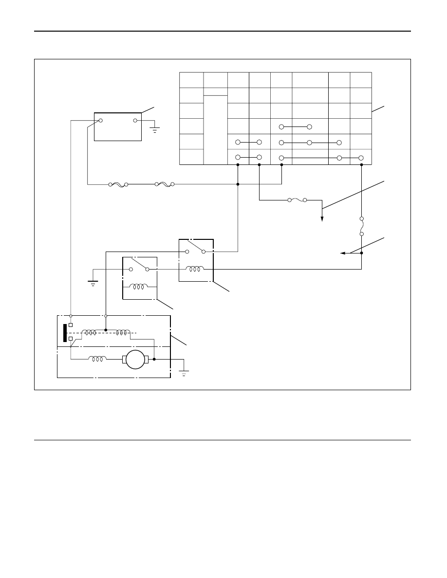
RELATION BETWEEN STARTER SWITCH AND STARTER
M
Key
Position
B1
B2
ACC
IG1
IG2
ST
LOCK
Key
Removed
Inserted
OFF
ACC
ON
START
B
S
Battery
+
-
2
1
7
3
4
5
6
Legend
(1)
Starter Switch
(2)
To Generator
(3)
To QOS4 Control
(4)
Starter Relay
(5)
Immobilizer Relay (for Europe)
(6)
Magnetic Switch
(7)
Battery
065R200029
ENGINE ELECTRICAL 6D – 7
ON-VEHICLE SERVICE
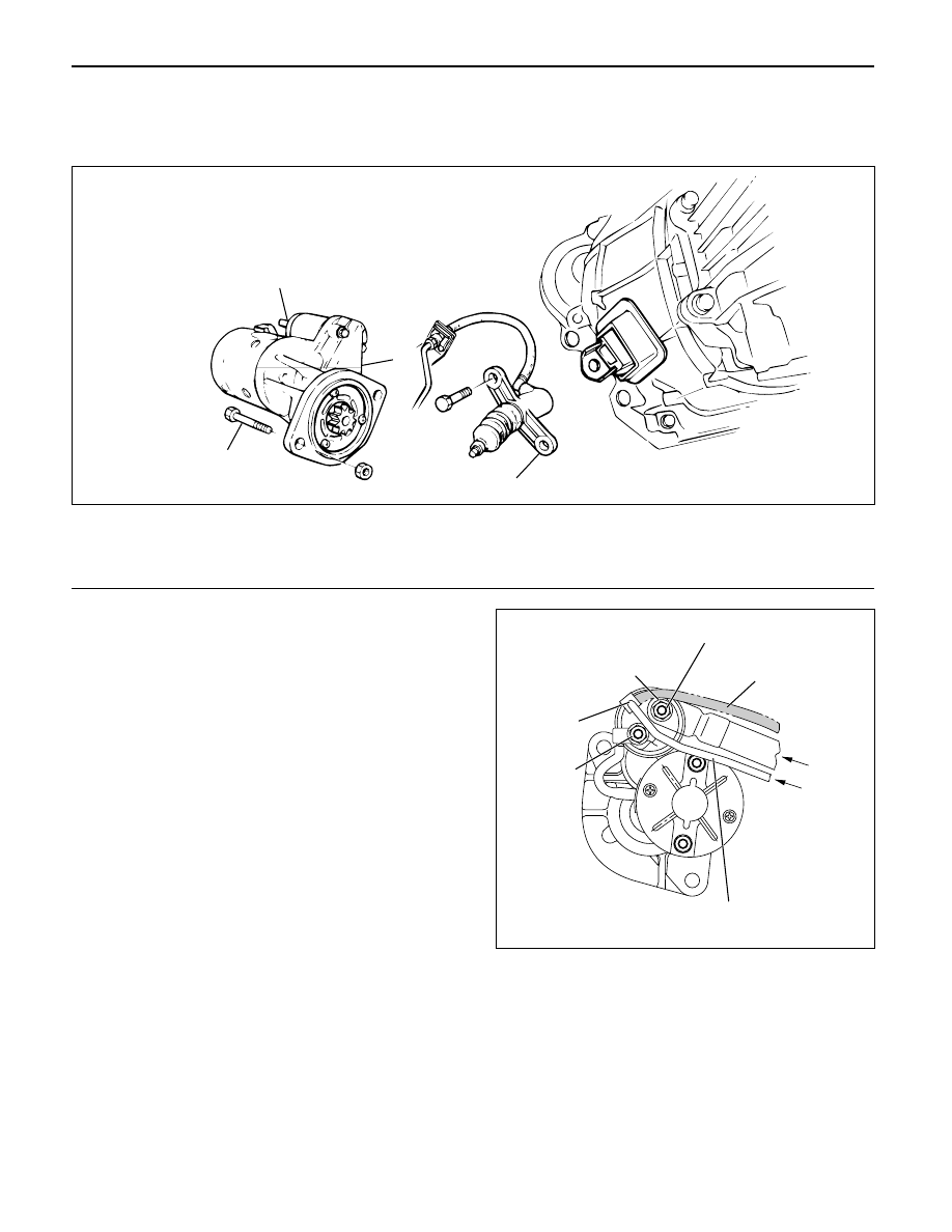
STARTER
REMOVAL
1 Battery ground cable
2 Remove the slave cylinder and bind with wire it to
the frame.
3 Disconnect the connector from terminals “B” and
“S”.
4. Remove mounting bolts
5. Remove starter assembly
INSTALLATION
1. Install starter assembly, tighten the fixing bolt and
nut to the specified torque.
Torque: 94 N·m (9.6 kg·m/69 lb ft)
2. Reconnect the starter terminals.
CAUTION: When installing the starter motor wiring,
do not allow the S-circuit wiring to obstruct the B-
circuit terminal.
Install the wiring exactly as shown on the attached
illustration.
If S-circuit wiring obstructs the B-circuit terminal,
harness cover breakage and short circuiting may
occur.
2-1. Install the wire harness from the battery to the
terminal “B” with tightening torque 8.6 N·m
(0.88 kg·m/6.4 lb·ft).
2-2. Cover the terminal “B” together with wire
harness.
2-3. Connect the wire harness from starter relay to
the terminal “S”.
3. Install the clutch slave cylinder, tighten the fixing
bolt and nut to the specified torque.
Torque: 78 N·m (8.0 kg·m/58 lb·ft)
1
3
2
4
Legend
(1)
Clutch Slave Cylinder
(2)
Magnetic Switch
(3)
Bolt
(4)
Starter Assembly
065RW00003
Do not recommend
wiring route.
Recommend wiring route
from S terminal.
From
battery
From
starter relay
Terminal B
Terminal M
Terminal S
In this area,
Scratch to break the wire
cover and make shortage.
065RW00002
Нет комментариевНе стесняйтесь поделиться с нами вашим ценным мнением.
Текст