Opel Frontera UBS. Service manual — part 969
3C – 8 FRONT SUSPENSION
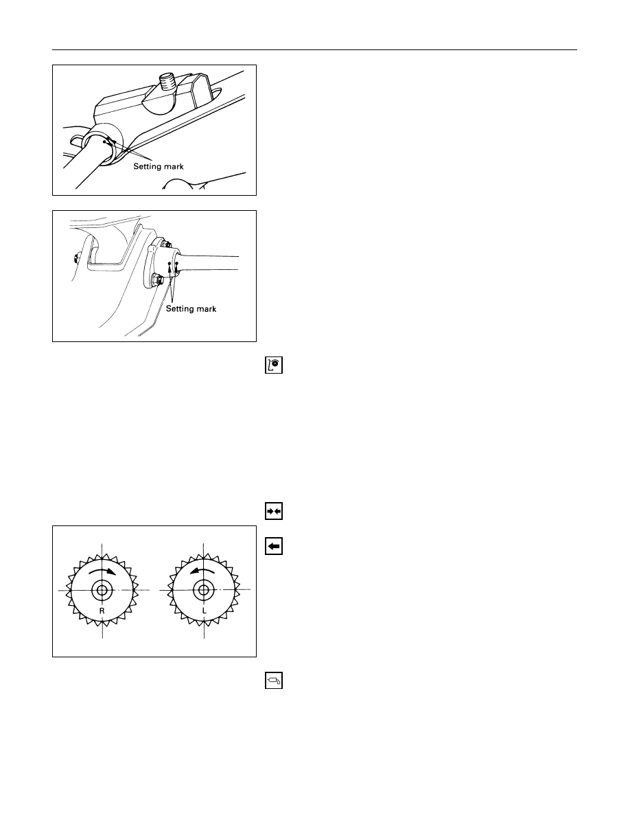
2. Height Control Arm
Apply the setting marks to the height control arm and
torsion bar.
3. Torsion Bar
Apply the setting marks to the torsion bar and lower
control arm.
INSPECTION AND REPAIR
Make necessary correction or parts replacement if wear,
damage, corrosion or any other abnormal condition are
found through inspection.
Check the following parts:
•
Torsion bar
•
Height control arm
•
Adjust bolt
•
Rubber seat
INSTALLATION
3. Torsion Bar
Make sure the bars are on their correct respective
sides.
Apply grease to the serrated portions.
FRONT SUSPENSION 3C – 9
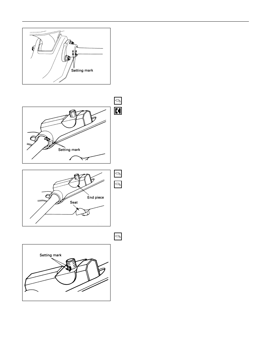
Align the setting marks.
2. Height Control Arm
Apply grease to the portion that fits into the bracket.
Align the setting marks.
Apply grease to the bolt portion of the end piece.
Apply grease to the portion of the seat that fits into
the bracket.
Apply grease to the serrated portions.
1. Adjust Bolt and Seat
Turn ther adjust bolt to the setting mark applied
during disassembly.
NOTE:
Adjust the trim height. Refer to “Front End Alignment” in
section 3A.
3C – 10 FRONT SUSPENSION
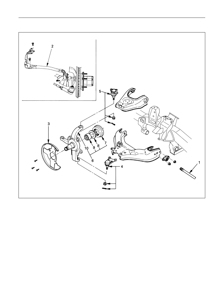
KNUCKLE
Removal Steps
1.
Torsion bar
2.
Wheel speed sensor
(if equipped with ABS)
3.
Back plate
4.
Lower ball joint
5.
Upper ball joint
6.
Knuckle assembly
7.
Oil seal
8.
Thrust washer
9.
Needle bearing
10.
Knuckle
Installation Steps
10.
Knuckle
9.
Needle bearing
8.
Thrust washer
7.
Oil seal
6.
Knuckle assembly
5.
Upper ball joint
4.
Lower ball joint
3.
Back plate
2.
Wheel speed sensor
(if equipped with ABS)
1.
Torsion bar
FRONT SUSPENSION 3C – 11
REMOVAL
Preparation:
1)
Raise the vehicle and support the frame with suitable
safety stands.
2)
Remove wheel and tire assembly. Refer to “Wheels
and Tires” in section 3E.
3)
Remove the brake caliper. Refer to “Brakes” in section
5.
4)
Remove the hub assembly. Refer to “Hub and Disk” in
section 4C.
5)
Remove outer track rod from the knuckle. Refer to
“Steering Linkage” in section 2A.
1. Torsion Bar
Loosen torsion bar by height control arm adjust bolt.
Refer to “Torsion bar” in this section.
2. Wheel speed sensor (if equipped with ABS)
3. Back Plate
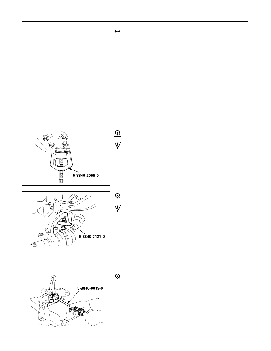
4. Lower Ball Joint
Remover: 5-8840-2005-0 (J-29107)
CAUTION:
Be careful not to break the ball joint boot.
5. Upper Ball Joint
Remover: 5-8840-2121-0 (J-36831)
CAUTION:
Be careful not to break the ball joint boot.
6. Knuckle Assembly
7. Oil Seal
8. Washer
9. Needle Bearing
Remover: 5-8840-0019-0 (J-23907)
Нет комментариевНе стесняйтесь поделиться с нами вашим ценным мнением.
Текст