Opel Frontera UBS. Service manual — part 970
3C – 12 FRONT SUSPENSION
10. Knuckle
INSPECTION AND REPAIR
Make necessary correction or parts replacement if wear,
damage, corrosion or any other abnormal condition are
found through inspection.
Check the following parts:
•
Knuckle
•
Needle bearing
•
Thrust washer
INSTALLATION
10. Knuckle
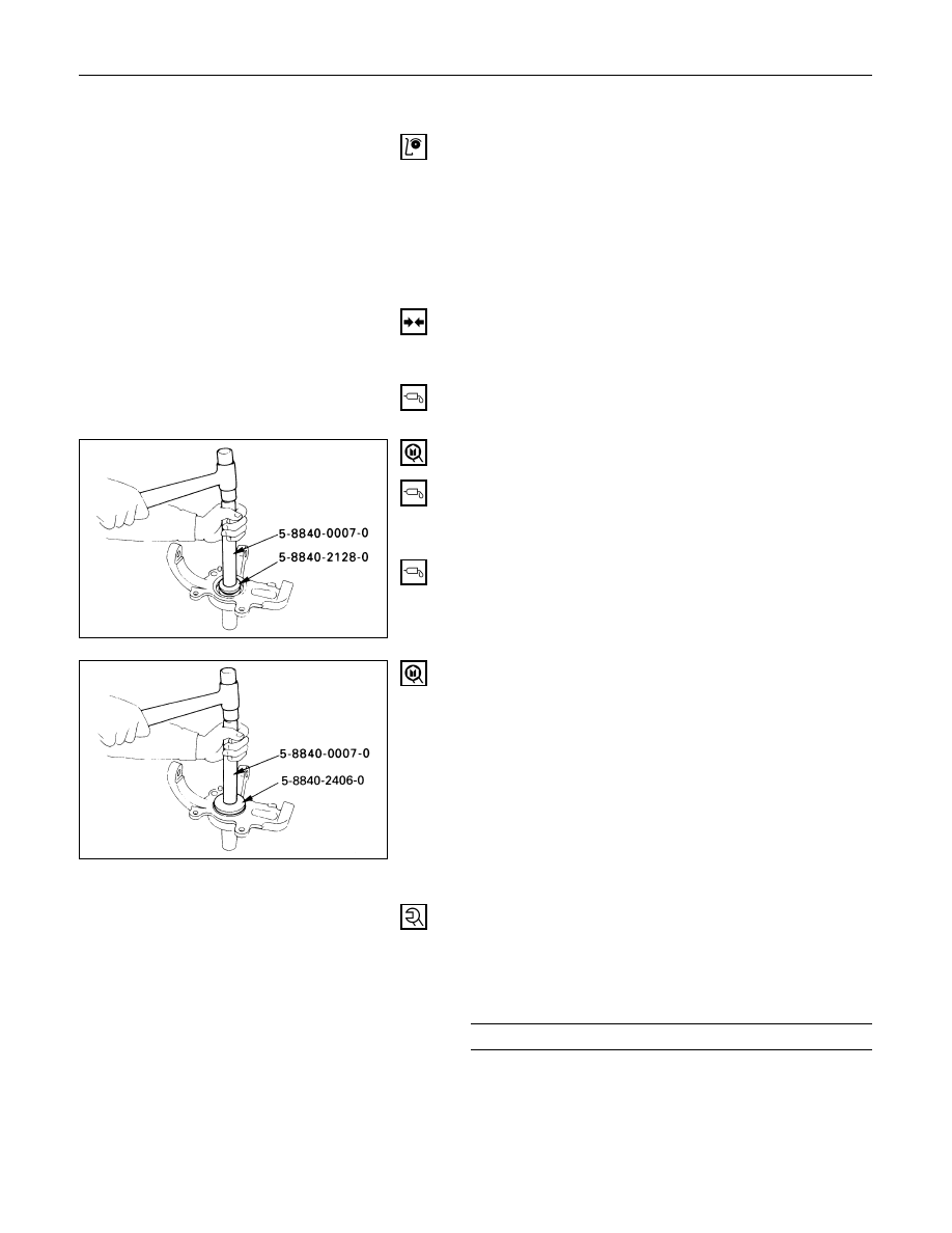
9. Needle Bearing
Before installation, apply appropriate amount of
multipurpose type grease to the new bearing (Approx.
5 g).
Installer: 5-8840-2128-0 (J-36838) and
5-8840-0007-0 (J-8092)
8. Washer
Apply multipurpose type grease to the thrust washer,
and install it with chamfered side facing knuckle.
7. Oil Seal
Use a new oil seal, and apply multipurpose type
grease to the area surrounded by the lip (approx. 2 g).
After fitting the oil seal to the installer, drive it to the
knuckle using a hammer or bench press until the tool
front face contacts with the thrust washer.
Installer: 5-8840-2406-0 (J-41468)and
5-8840-0007-0 (J-8092)
6. Knuckle Assembly
5. Upper Ball Joint
Tighten the nut to the specified torque, with just
enough additional torque to align cotter pin holes.
Install new cotter pin.
Upper Ball Joint Nut Torque
N·m (kg·m/lb·ft)
98 (10.0 / 72)

FRONT SUSPENSION 3C – 13
4. Lower Ball Joint
Tighten the nut to the specified torque, with just
enough additional torque to align cotter pin holes.
Install new cotter pin.
Lower Ball Joint Nut Torque
N·m (kg·m/lb·ft)
147 (15.0 / 108)
3. Back Plate
2. Wheel Speed Sensor (if equipped with ABS)
Tighten the bolt to the specified torque.
Wheel Speed Sensor Bolt Torque
N·m (kg·m/lb·in)
8 (0.8 / 69)
1. Torsion Bar
Refer to “Torsion Bar” in this section.
NOTE:
Adjust the trim height. Refer to “Front End
Alignment” in section 2A.
3C – 14 FRONT SUSPENSION
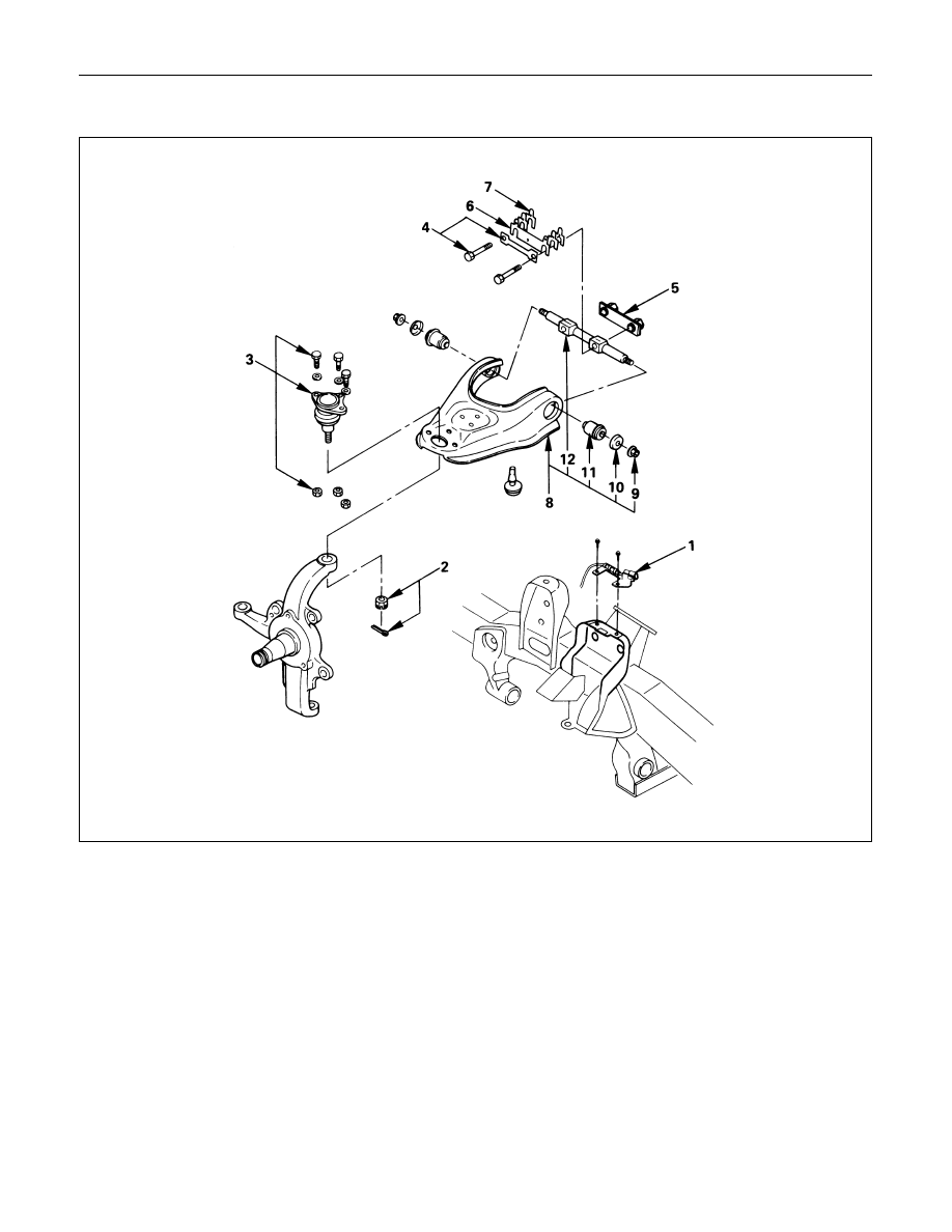
UPPER CONTROL ARM
Removal Steps
1.
Speed sensor cable (if equipped with
ABS)
2.
Nut and cotter pin
3.
Upper ball joint
4.
Bolt and plate
5.
Nut assembly
6.
Camber shims
7.
Caster shims
8.
Upper control arm assembly
9.
Nut
10.
Plate
11.
Bushing
12.
Fulcrum pin
Installation Steps
12.
Fulcrum pin
11.
Bushing
10.
Plate
9.
Nut
8.
Upper control arm assembly
7.
Caster shims
6.
Camber shims
5.
Nut assembly
4.
Bolt and plate
3.
Upper ball joint
2.
Nut and cotter pin
1.
Speed sensor cable (if equipped with
ABS)
FRONT SUSPENSION 3C – 15
REMOVAL
Preparation:
1)
Raise the vehicle and support the frame with suitable
safety stands.
2)
Remove wheel and tire assembly. Refer to “Wheels
and Tires” in section 3E.
3)
Remove the brake caliper and disconnect flexible hose.
Refer to “Brakes” in section 5.
4)
Support lower control arm with a jack.
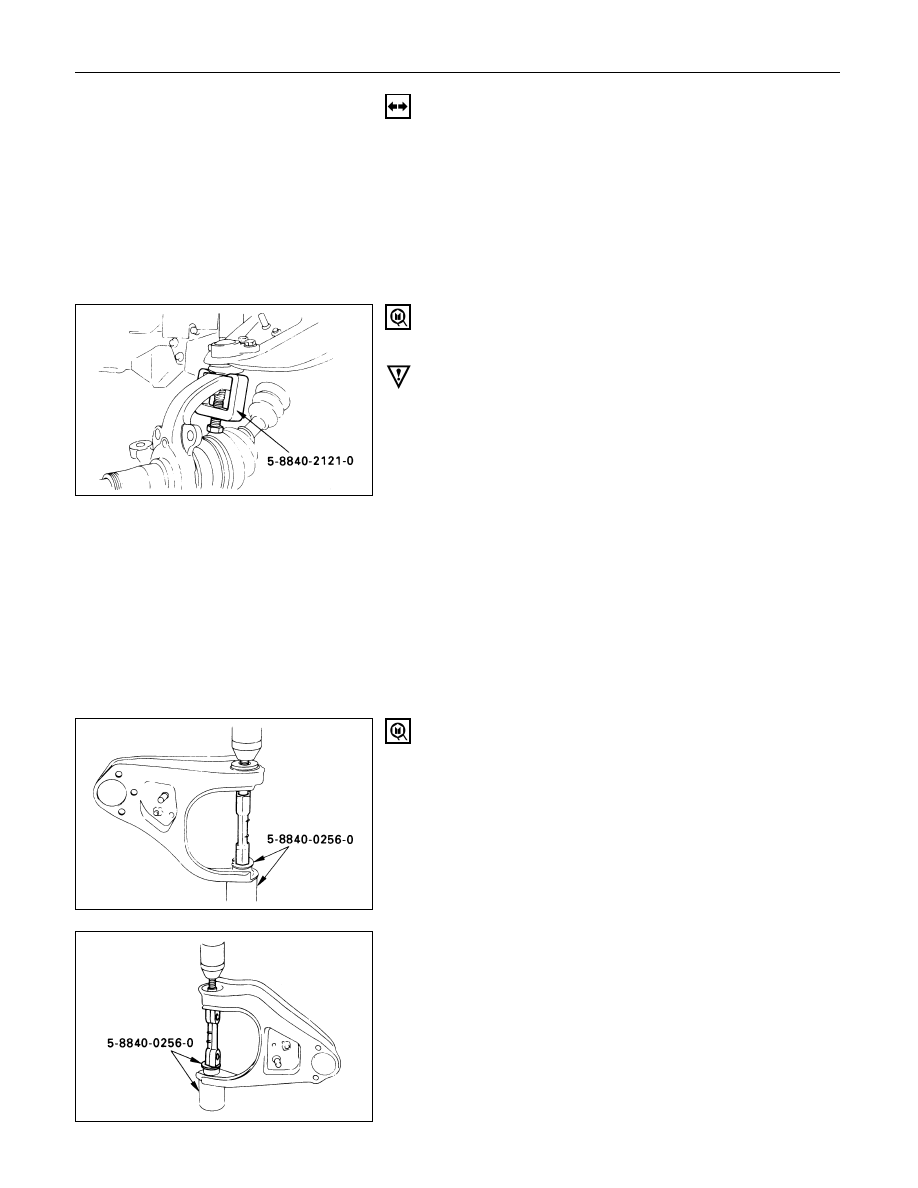
1. Speed Sensor Cable (if equipped with ABS)
2. Nut and Cotter Pin
Remove the upper ball joint from the knuckle.
Remover: 5-8840-2121-0 (J-36831)
CAUTION:
Be careful not to break the ball joint boot.
3. Upper Ball Joint
4. Bolt and Plate
5. Nut Assembly
6. Camber Shims
Note the positions and number of shims.
7. Caster Shims
Note the positions and number of shims.
8. Upper Control Arm Assembly
9. Nut
10. Plate
11. Bushing
Remover: 5-8840-0256-0 (J-29755)
12. Fulcrum Pin
Нет комментариевНе стесняйтесь поделиться с нами вашим ценным мнением.
Текст