Opel Frontera UBS. Service manual — part 2265
6E–96
6VE1 3.5 ENGINE DRIVEABILITY AND EMISSIONS
Engine Cranks But Will Not Run
D06R200100
6E–97
6VE1 3.5L ENGINE DRIVEABILITY AND EMISSIONS
D06R200081

6E–98
6VE1 3.5 ENGINE DRIVEABILITY AND EMISSIONS
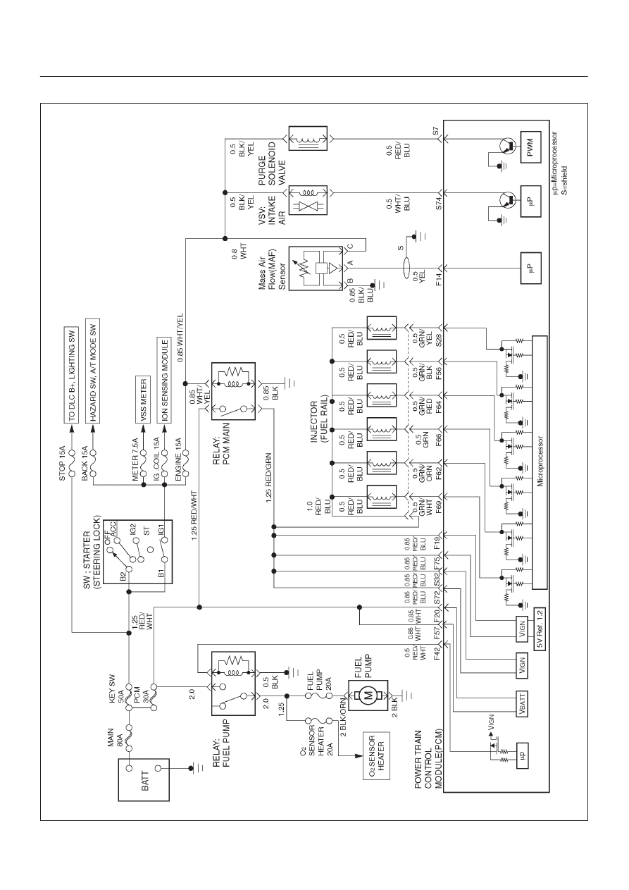
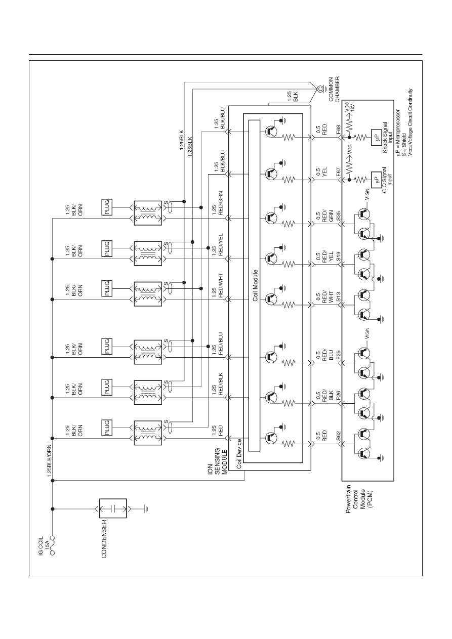
Circuit Description
The electronic Ignition system uses a coil -at-plug method
of spark distribution. In this type of ignition system, the
powertrain control module (PCM) triggers the correct
driver outside the Ignition Current Sense System (ICSS),
which then triggers the correct ignition coil based on the
58X signal received from the crankshaft position sensor
(CKP). The spark plug connected to the coil fires when
the ICSS opens the ground circuit for the coil’s primary
circuit.
During crank, the PCM monitors the CKP 58X signal. The
CKP signal is used to determine which cylinder will fire
first. After the CKP 58X signal has been processed by the
PCM, it will command all six injectors to allow a priming
shot of fuel for all the cylinders. After the priming, the
injectors are left “OFF” during the next six 58X reference
pulses from the CKP. This allows each cylinder a chance
to use the fuel from the priming shot. During this waiting
been received by the PCM. The ION sensor signal allows
the PCM to operate the injectors sequentially based on
camshaft position. If the camshaft position signal is not
present at start - up, the PCM will begin sequential fuel
delivery with a 1 -in-6 chance that fuel delivery is correct.
The engine will run without a ION sensor signal, but will
set a DTC code.
Diagnostic Aids
An intermittent problem may be caused by a poor
connection, rubbed - through wire insulation or a wire
broken inside the insulation. Check for the following
items:
D
Poor connection or damaged harness-Inspect the
PCM harness and connectors for improper mating,
broken locks, improperly formed or damaged
terminals, poor terminal-to-wire connection, and
damaged harness.
D
Faulty engine coolant temperature sensor-Using a
Tech 2, compare engine coolant temperature with
intake air temperature on a completely cool engine.
Engine coolant temperature should be within 10
°
C of
intake air temperature. If not, replace the ECT sensor.
Test Description
Number(s) below refer to the step number(s) on the
Diagnostic Chart.
5. An obvious cause of low fuel pressure would be an
empty fuel tank.
6. The engine will easily start and run if a few injectors
are disabled. It is not necessary to test all injectors
at this time since this step is only a test to verify that
all of the injectors have not been disabled by fuel
contamination.
7. A blinking test light verifies that the PCM is
monitoring the 58X crankshaft reference signal and
is capable of activating the injectors. If there is an
open or shorted driver circuit, DTCs 201 – 206 and
a misfire DTC 300 – 306 should be set.
19. By using a spark tester, each ignition coil’s ability to
produce 25,000 volts is verified.
25. If there is an open or shorted driver circuit, DTCs
201 – 206 and a misfire DTC 301 – 306 should be
set. All six injector driver circuits can be checked at
one time without removing the intake manifold if a J
39021 – 95 test light is available. This is the
alternative procedure:
D
With the ignition “OFF”, disconnect the gray
connector located at the rear of the air filter, attached
to a bracket on the purge canister.
D
Connect test light J 39021 – 95 to the connector. Do
any of the light constantly illuminate or fail to blink
when the engine is cranked? If so, repair the short or
open circuit, or replace the PCM if indicated.
This procedure only tests the driver circuit as far as the
test connection, so step 31 is added to test the circuit all
the way to the injector.
Engine Cranks But Will Not Run
Step
Action
Value(s)
Yes
No
1
Was the “On-Board Diagnostic (OBD) System Check”
performed?
—
Go to
Step 2
Go to
OBD
System
Check
2
Check the ignition coil fuse, the engine fuse, and the
PCM fuse.
Was a fuse blown?
—
Go to
Step 3
Go to
Step 4
3
Check for a short to ground and replace the fuse.
Is the action complete?
—
Verify repair
—

6E–99
6VE1 3.5L ENGINE DRIVEABILITY AND EMISSIONS
Engine Cranks But Will Not Run
(Cont'd)
Step
No
Yes
Value(s)
Action
4
1. Ignition “OFF”, install a fuel pressure gauge at the
test fitting on the fuel supply line in the engine
compartment. (Use a shop cloth to absorb any fuel
leakage while making the connection.)
2. Ignition “ON”, observe the fuel pressure.
Is the fuel pressure within the specified values, and
does it hold steady?
285 - 375 kPa
(43 – 55 psi)
Go to
Step 6
Go to
Step 5
5
Is any fuel pressure indicated?
—
Go to
Fuel
System
Electrical Test
Go to
Fuel
System
Diagnosis
6
Install the switch box J 39021–2 at the injector test
connector and activate an injector.
Did the fuel pressure drop when the injector was
activated?
—
Go to
Step 7
Go to
Step 18
7
Install an injector test light at the #2 cylinder injector
harness connector.
Does the light blink when the engine is cranked?
—
Go to
Step 8
Go to
Step 24
8
1. Ignition “ OFF”.
2. Disconnect the 11-pin connector at the ION sensing
module.
3. With a test light to B + , probe each of the 6 exposed
ION sensing module pins, one at a time, while the
engine is cranked. (Use the gray narrow Metri - Pak
flexible female connector from the J - 35616 kit to
make the pin accessible.)
Does the light flash at each pin when the engine is
cranked?
—
Go to
Step 12
Go to
Step 9
9
1. Remove the 4-pin connector at the ION sensing
module.
2. Ignition “ ON”.
3. Use a test light at the harness connector to verify
that the module is being supplied with B + and
ground.
Was a problem found?
—
Go to
Step 10
Go to
Step 11
10
Repair the open ignition feed circuit or ground circuit to
the ION sensing module.
Is the action complete?
—
Verify repair
—
11
Repair the ION sensing module.
Is the action complete?
—
Verify repair
—
12
1. Reconnect the ION sensing module 11-pin
connector.
2. Remove the electrical connector from each coil.
3. With a test light to B+, probe each of the coil
connectors at the wire which runs to the ION
sensing module.
Does the light flash at each coil connector when the
engine is cranked?
—
Go to
Step 14
Go to
Step 13
13
Check for an open circuit between the coil and ION
sensing module.
Is the action complete?
—
Verify repair
—
Нет комментариевНе стесняйтесь поделиться с нами вашим ценным мнением.
Текст