Opel Frontera UBS. Service manual — part 2264

6E–92
6VE1 3.5 ENGINE DRIVEABILITY AND EMISSIONS
No Service Vehicle Soon (SVS) Lamp
Step
Action
Value(s)
Yes
No
1
Was the “On-Board Diagnostic (OBD) System Check”
performed?
—
Go to
Step 2
Go to
OBD
System
Check
2
Attempt to start the engine.
Does the engine start?
—
Go to
Step 3
Go to
Step 6
3
Check the meter fuse for the instrument cluster ignition
feed circuit.
Is the fuse OK?
—
Go to
Step 4
Go to
Step 16
4
Ignition “ON”, probe the ignition feed circuit at the
cluster connector with a test light to ground.
Is the test light “ON”?
—
Go to
Step 5
Go to
Step 13
5
1. Ignition “OFF”.
2. Disconnect the PCM.
3. Jumper the SVS lamp driver circuit at the PCM
connector to ground.
4. Ignition “ON”.
Is the SVS lamp “ON”?
—
Go to
Step 10
Go to
Step 11
6
Check the PCM ignition feed and battery feed fuses (15
A engine fuse and 15 A PCM fuse).
Are both fuses OK?
—
Go to
Step 7
Go to
Step 15
7
1. Ignition “OFF”.
2. Disconnect the PCM.
3. Ignition “ON”.
4. Probe the ignition feed circuit at the PCM harness
connector with a test light to ground.
Is the test light “ON”?
—
Go to
Step 8
Go to
Step 12
8
Probe the battery feed circuit at the PCM harness
connector with a test light to ground.
Is the test light “ON”?
—
Go to
Step 9
Go to
Step 14
9
Check for a faulty PCM ground connection.
Was a problem found?
—
Verify repair
Go to
Step 10
10
Check for damaged terminals at the PCM.
Was a problem found?
—
Verify repair
Go to
Step 17
11
Check for an open SVS lamp driver circuit between the
PCM and the SVS lamp.
Was a problem found?
—
Verify repair
Go to
Step 18
12
Substitute a known “good” relay for the PCM main
relay.
Was the malfunction fixed?
—
Verify repair
Go to
Step 13
13
Repair the open in the ignition feed circuit.
Is the action complete?
—
Verify repair
—
14
Locate and repair the open PCM battery feed circuit.
Is the action complete?
—
Verify repair
—

6E–93
6VE1 3.5L ENGINE DRIVEABILITY AND EMISSIONS
No Service Vehicle Soon (SVS) Lamp
(Cont'd)
Step
No
Yes
Value(s)
Action
15
Locate and repair the short to ground in the PCM
ignition feed circuit or PCM battery feed circuit.
Is the action complete?
—
Verify repair
—
16
Locate and repair the short to ground in the ignition
feed circuit to the instrument cluster, and replace the
fuse.
Is the action complete?
—
Verify repair
—
17
Replace the PCM.
IMPORTANT: The replacement PCM must be
programmed. Refer to
PCM in ON-Vehicle Service for
procedures.
And also refer to latest Service Bulletin.
Check to see if the Latest software is released or not.
And then Down Load the LATEST PROGRAMMED
SOFTWARE to the replacement PCM.
Is the action complete?
—
Verify repair
—
18
Check the SVS lamp driver circuit for a poor connection
at the instrument panel connector.
Was a problem found?
—
Verify repair
Go to
Instrument
Panel in
Electrical
Diagnosis
6E–94
6VE1 3.5 ENGINE DRIVEABILITY AND EMISSIONS
Service Vehicle Soon (SVS) Lamp “ON” Steady
D06R200111
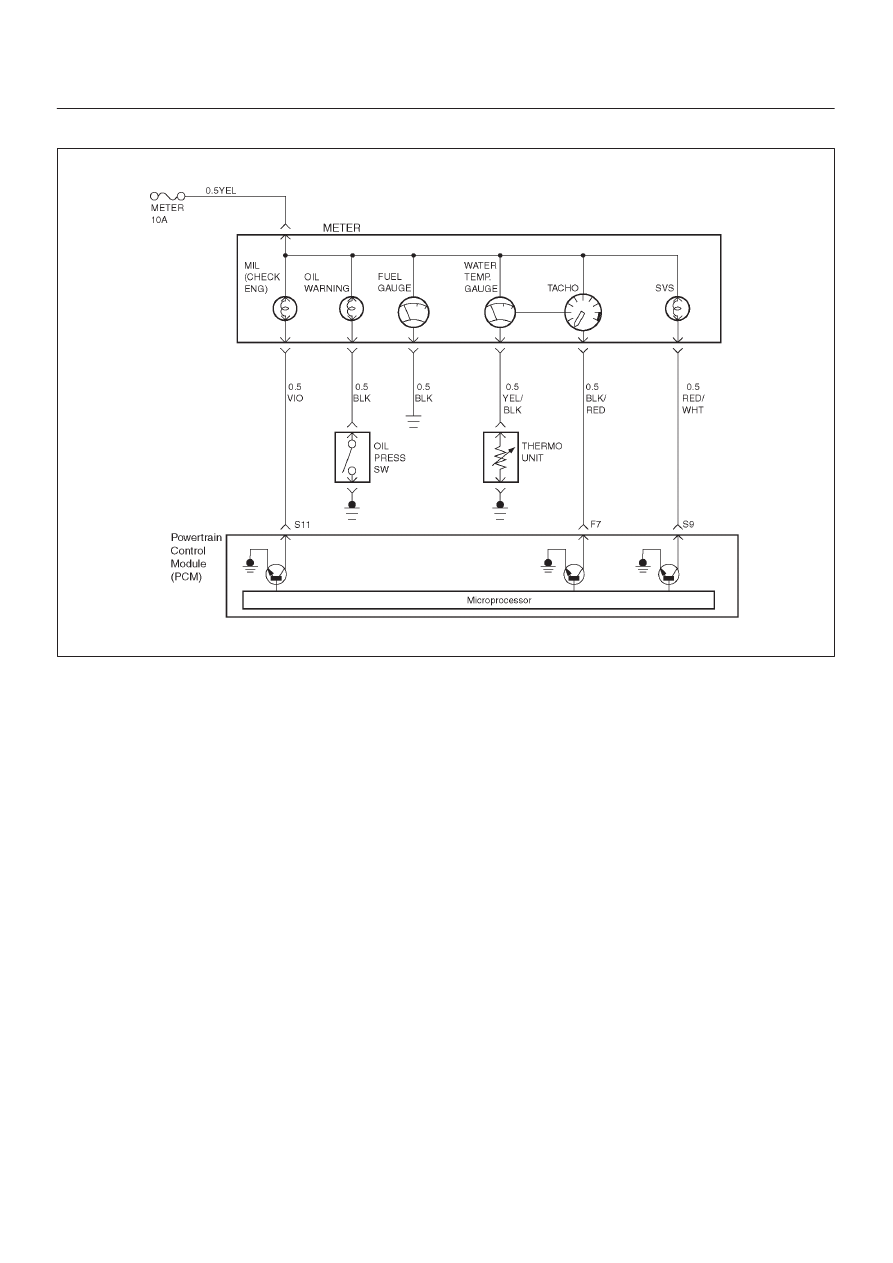
Circuit description
The Service Vehicle Soon (SVS) lamp is a lamp which
added the function of immobi warning to the Reduced
Power Lamp (RPL).
The SVS lamp should always be illminated and steady
with ignition “ON” and the engine stopped. Ignition feed
voltage is supplied directly to the SVS lamp indicator. The
powertrain control module (PCM) turns the SVS lamp
“ON” by grounding the SVS lamp driver circuit.
The RPL should not remain “ON” with the engine running
and no DTC(s) set. A steady SVS lamp with the engine
running and no DTC(s) suggests a short to ground in the
SVS lamp driver circuit.
Diagnostic Aids
An intermittent may be caused by a poor connection,
rubbed-through wire insulation, or a wire broken inside
the insulation. Check for the following items:
D
Poor connection or damaged harness – Inspect the
PCM harness and connectors for improper mating,
broken locks, improperly formed or damaged
terminals, poor terminal-to-wire connection, and
damaged harness.
Test Description
Number(s) below refer to the step number(s) on the
Diagnostic Chart.
2. If the SVS lamp does not remain “ON” when the
PCM is disconnected, the SVS lamp driver wiring is
not faulty.
3. If the SVS lamp driver circuit is OK, the instrument
panel cluster is faulty.
6. This vehicle is equipped with a PCM which utilizes
an electrically erasable programmable read only
memory (EEPROM). When the PCM is replaced,
the new PCM must be programmed. Refer to
PCM
Replacement and Programming Procedures in
Powertrain Control Module (PCM) and Sensors.

6E–95
6VE1 3.5L ENGINE DRIVEABILITY AND EMISSIONS
Service Vehicle Soon (SVS) Lamp “ON” Steady
Step
Action
Value(s)
Yes
No
1
Was the “On-Board diagnostic (OBD) System Check”
performed?
—
Go to
Step 2
Go to
OBD
System
Check
2
1. Ignition “OFF”, disconnect PCM.
2. Ignition “ON”, observe the SVS lamp.
Is the SVS lamp “ON”?
—
Go to
Step 3
Go to
Step 5
3
1. Ignition “OFF”, disconnect the instrument panel
cluster.
2. Check the SVS lamp driver circuit between the PCM
and the instrument panel cluster for a short to
ground.
3. If a problem is found, repair as necessary.
Was the SVS lamp driver circuit shorted to ground?
—
Go to
OBD
System
Check
Go to
Step 4
4
Replace the instrument panel cluster.
Is the action complete?
—
Go to
OBD
System
Check
—
5
1. Ignition “OFF”, reconnect the PCM.
2. Ignition “ON”, reprogram the EEPROM. Refer to
On-Vehicle Service in Powertrain Control Module
and Sensors for procedures.
3. Using the Tech 2 output controls function, select
RPL dash lamp control and command the RPL
(SVS lamp) “OFF”. (Refer to the Miscellaneous
test)
Did the SVS lamp turn “OFF”?
—
Go to
OBD
System
Check
Go to
Step 6
6
Replace the PCM.
IMPORTANT: The replacement PCM must be
programmed. Refer to
On-Vehicle Service in
Powertrain Control Module and Sensors for
procedures.
And also refer to latest Service Bulletin.
Check to see if the Latest software is released or not.
And then Down Load the LATEST PROGRAMMED
SOFTWARE to the replacement PCM.
Is the action complete?
—
Go to
OBD
System
Check
—
Нет комментариевНе стесняйтесь поделиться с нами вашим ценным мнением.
Текст