Opel Frontera UBS. Service manual — part 2367
6E–504
6VE1 3.5 ENGINE DRIVEABILITY AND EMISSIONS
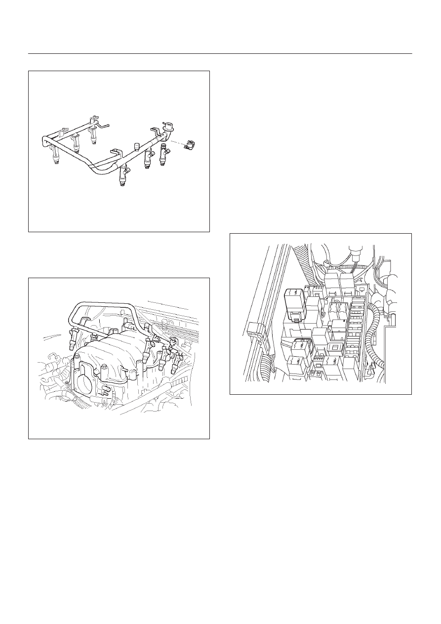
3. Install the fuel injector on the fuel rail.
040RY00001
4. Use new fuel injector retainer clips to retain the fuel
injector to the fuel rail.
5. Coat the end of the fuel injector with gasoline.
6. Install the fuel rail. Refer to
Fuel Rail section.
014RW164
7. Install the common chamber. Refer to
Common
Chamber in Engine Mechanical section.
8. Install the engine cover.
9. Connect the negative battery cable.
Fuel Metering System
Fuel Pressure Relief Procedure
CAUTION: To reduce the risk of fire and personal
injury, there are necessary to relieve the fuel system
pressure before filler and gauge unit servicing the
fuel system components.
CAUTION: After relieving the system pressure, a
small amount of fuel may be released when servicing
fuel lines or connections. Reduce the chance of
personal injury by covering the fuel line fittings with
a shop towel before you disconnect the fittings. The
towels will absorb any fuel that may leak out. When
the disconnect is completed, place the towel in an
approved container.
1. Remove the fuel cap.
2. Remove the fuel pump relay from the underhood
relay box. Refer to
Fuel Pump Relay section.
060R200195
3. Start the engine and allow it to stall.
4. Crank the engine for 30 seconds.
5. Disconnect the negative battery cable.
6E–505
6VE1 3.5L ENGINE DRIVEABILITY AND EMISSIONS
Fuel Pump Assembly
Removal Procedure
Refer to
Fuel Tank section.
060R200246
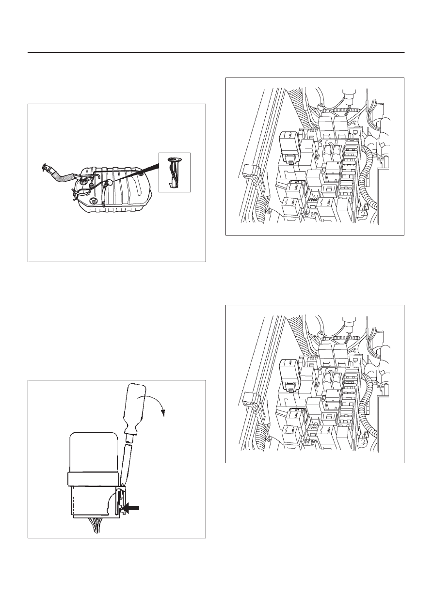
Fuel Pump Relay
Removal Procedure
1. Remove the fuse and relay box cover from under the
hood.
2. Consult the diagram on the cover to determine which
is the correct relay.
3. Insert a small screwdriver into the catch slot on the
forward side of the fuel pump relay.
D
The screwdriver blade will release the catch inside.
D08RY00291
4. Pull the relay straight up and out of the fuse and relay
box.
060R200195
Installation Procedure
1. Insert the relay into the correct place in the fuse and
relay box with the catch slot facing forward.
2. Press down until the catch engages.
D
An audible “click” will be heard.
060R200195
3. Install the fuse and relay box cover.
6E–506
6VE1 3.5 ENGINE DRIVEABILITY AND EMISSIONS
Fuel Rail Assembly
Removal Procedure
NOTE:
D
Do not attempt to remove the fuel inlet fitting on the
fuel rail. It is staked in place. Removing the fuel inlet
fitting will result in damage to the fuel rail or the
internal O-ring seal.
D
Use care when removing the fuel rail assembly in
order to prevent damage to the injector electrical
connector terminals and the injector spray tips.
D
Fittings should be capped and holes plugged during
servicing to prevent dirt and other contaminants from
entering open lines and passages.
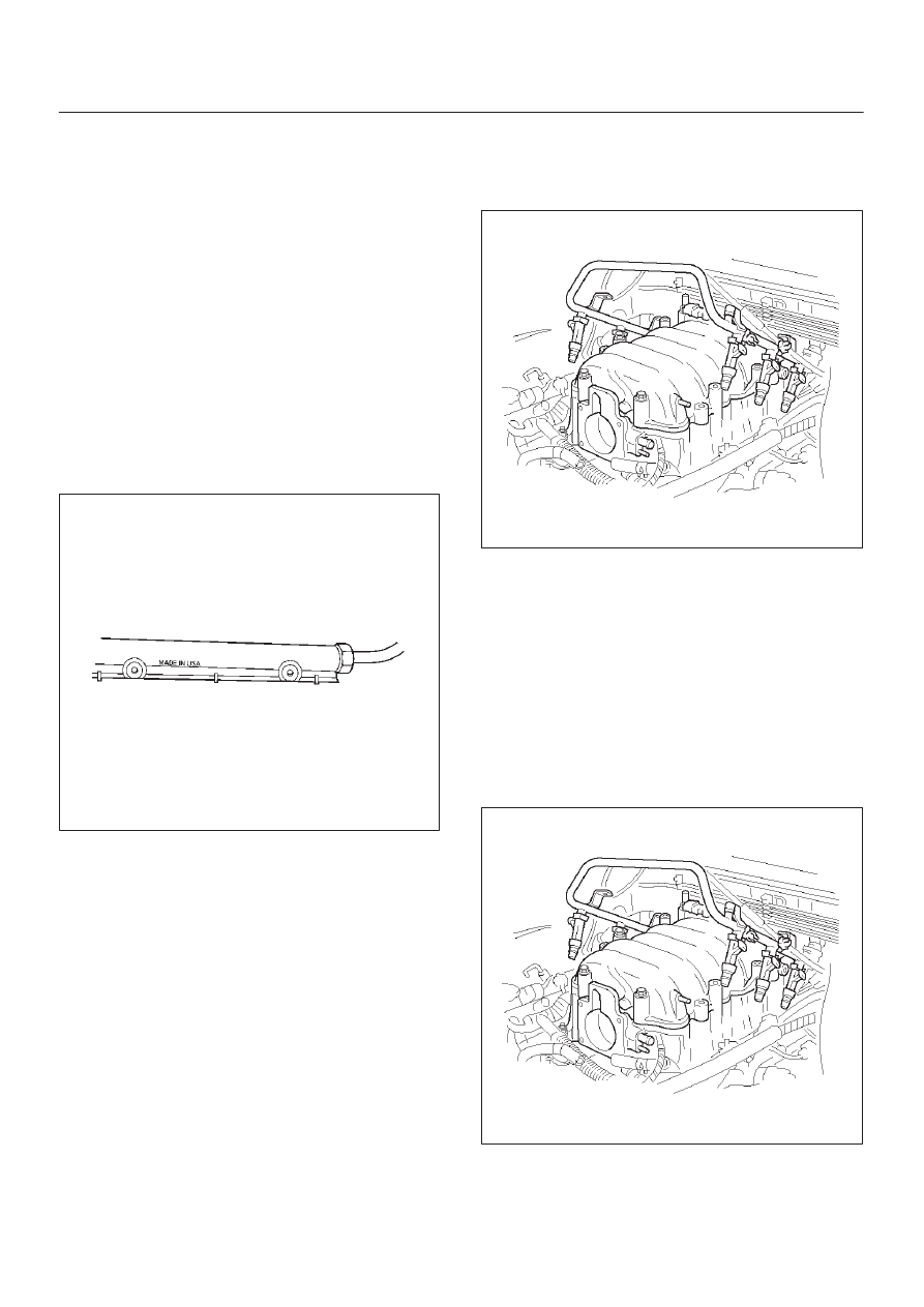
IMPORTANT:
An eight-digit identification number is
stamped on the side of the fuel rail. Refer to this number
when you service the fuel rail or when a replacement part
is required.
014RY00008
Before removal, the fuel rail assembly may be cleaned
with a spray type engine cleaner. Follow the spray
package instructions. Do not immerse the fuel rails in
liquid cleaning solvent.
1. Depressurize the fuel system. Refer to Fuel Pressure
Relief Procedure in this Section.
2. Disconnect the negative battery cable.
3. Remove the engine cover.
4. Disconnect the throttle position sensor electrical
connector from throttle body.
5. Disconnect the connectors from manifold absolute
pressure sensor, solenoid valve, electric vacuum
sensing valve.
6. Disconnect the vacuum hose on canister VSV and
positive crankcase ventilation hose.
7. Remove the common chamber. Refer to the common
chamber in Engine Mechanical section.
1. Lift up carefully on the fuel injectors. Do not
separate the fuel injectors from the fuel rail.
2. If an injector becomes separated from the fuel
rail, the infector O-ring seals and the retainer clip
must be replaced.
3. Drain residual fuel into an approved container.
014RW164
8. If removal of the fuel pressure regulator is necessary,
refer to
Fuel Pressure Regulator section.
9. If removal of the fuel injectors is necessary, refer to
Fuel Injectors section.
Installation Procedure
1. If the fuel injectors were removed, install them. Refer
to
Fuel Injectors section.
2. If the fuel pressure regulator was removed, install it.
Refer to
Fuel Pressure Regulator section.
3. Install the common chamber. Refer to common
chamber in engine Mechanical section.
014RW164
4. Connect the vacuum hose on Canister VSV and
positive crankcase ventilation hose.
6E–507
6VE1 3.5L ENGINE DRIVEABILITY AND EMISSIONS
5. Connect the connectors to manifold absolute
pressure sensor, solenoid valve, electric vacuum
sensing valve.
6. Connect the throttle position sensor electrical
connector to throttle body.
7. Install the engine cover.
8. Connect the negative battery cable.
9. Crank the engine until it starts. Cranking the engine
may take longer than usual due to trapped air in the
fuel rail and in the injectors.
Fuel Tank
Removal Procedure
Refer to
Fuel Tank section.
060R200244
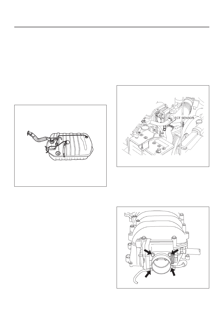
Throttle Body (TB)
Removal Procedure
1. Disconnect the negative battery cable.
2. Drain the cooling system. Refer to
Cooling System
section.
3. Disconnect the electrical connectors:
D
Throttle position (TP) sensor.
D
Intake air temperature (IAT) sensor. Refer to
Intake
Air Temperature Sensor section.
060RY00014
4. Disconnect the vacuum hose below the air horn.
5. Remove the intake air duct clamp.
6. Disconnect the intake air duct.
7. Disconnect the coolant lines from the throttle body.
8. Remove the bolts from the common chamber.
9. Remove the throttle body from the common chamber.
10. Remove the gasket from the common chamber.
060R200183
11. Remove the TP sensor. Refer to
Throttle Position
(TP) Sensor section.
Нет комментариевНе стесняйтесь поделиться с нами вашим ценным мнением.
Текст