Opel Frontera UBS. Service manual — part 2368
6E–508
6VE1 3.5 ENGINE DRIVEABILITY AND EMISSIONS
Inspection Procedure
NOTE: Do not use solvent of any type when you clean the
gasket surfaces on the intake manifold and the throttle
body assembly. The gasket surfaces and the throttle
body assembly may be damaged as a result.
D
If the throttle body gasket needs to be replaced,
remove any gasket material that may be stuck to the
mating surfaces of the manifold.
D
Do not leave any scratches in the aluminum casting.
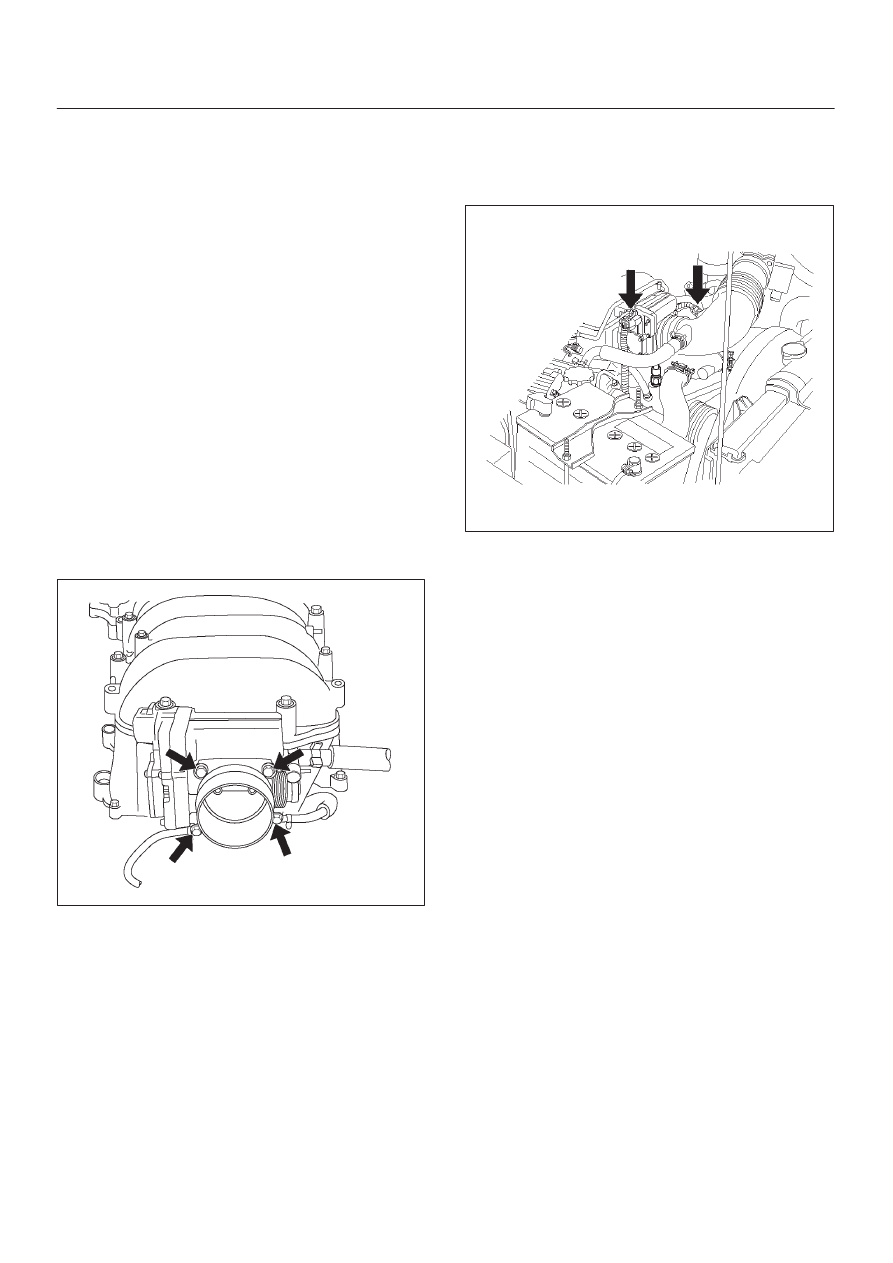
Installation Procedure
1. Install the TP sensor. Refer to
Throttle Position (TP)
Sensor section.
2. Install the gasket on the common chamber.
3. Install the throttle body on the common chamber.
4. Secure the gasket and the throttle body with the four
bolts.
D
The vacuum lines must be properly routed under
the throttle body before tightening the mounting
bolts.
Tighten
D
Tighten the throttle body mounting bolts to 10
N·m (87 lb in).
060R200183
5. Install the coolant lines.
6. Connect all the vacuum lines.
7. Install the intake air duct.
8. Tighten the intake air duct clamp.
9. Connect all the electrical connectors:
D
Throttle position (TP) sensor.
D
Intake air temperature (IAT) sensor. Refer to
Intake
Air Temperature Sensor section.
060RY00020
10. Install the accelerator cable assembly. Refer to
Accelerator Cable in Engine Speed Control System
section.
11. Fill the cooling system. Refer to
Cooling System
section.
12. Install the negative battery cable.
6E–509
6VE1 3.5L ENGINE DRIVEABILITY AND EMISSIONS
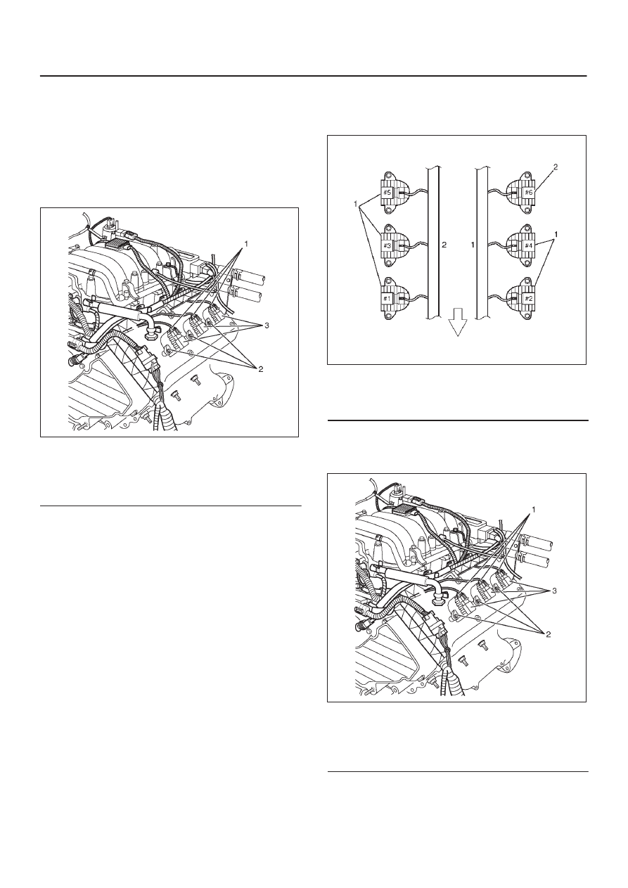
Electronic Ignition System
Removal Procedure
1. Disconnect the negative battery cable.
2. Disconnect the ignition coil connector at the ignition
coil assemblies.
3. Remove the two screws that secure the ignition coil
assemblies to the rocker cover.
060R200210
Legend
(1) Ignition Coil Connectors
(2) Bolts
(3) Ignition Coil Assemblies
4. Remove the ignition coil assemblies and the spark
plug boot from the spark plug.
D
Twist the ignition coil assemblies while pulling it
straight up.
5. Use the appropriate spark plug socket in order to
remove the spark plug from the engine.
Installation Procedure
NOTE: The plug must thread smoothly into the cylinder
head and be fully seated. Use a thread chaser if
necessary to clean the threads in the cylinder head.
Cross-threading or failure to fully seat the spark plug can
cause plug overheating, exhaust blow-by gases, or
thread damage. Do not overtighten the spark plugs. Over
tightening can cause aluminum threads to strip.
1. Install the spark plug in the engine. Use the
appropriate spark plug socket.
Tighten
D
Tighten the spark plug to 18 N·m (13 lb ft.).
2. Install the ignition coil assemblies and spark plug boot
over the spark plug.
CAUTION: Ignition coil assembly #6 is different
from ignition coil assembly #1 to #5. Ignition coil
assemblies #6 is short type. Be careful it when
installing ignition coil assembly of #6.
060RY00002
Legend
(1) Long Type Ignition Coil Assemblies (#1
∼
#5)
(2) Short Type Ignition Coil Assembly (#6)
3. Install ignition coil assemblies and tighten the fixing
bolts to the specified torque.
Torque: 4 N·m (35.4 Ib in)
060R200210
Legend
(1) Ignition Coil Connectors
(2) Bolts
(3) Ignition Coil Assemblies
4. Connect the ignition coil connector at the ignition coil
assemblies.
5. Connect the negative battery cable.
6E–510
6VE1 3.5 ENGINE DRIVEABILITY AND EMISSIONS
Catalytic Converter
Removal and Installation Procedure
Refer to
Engine Exhaust in Engine section.
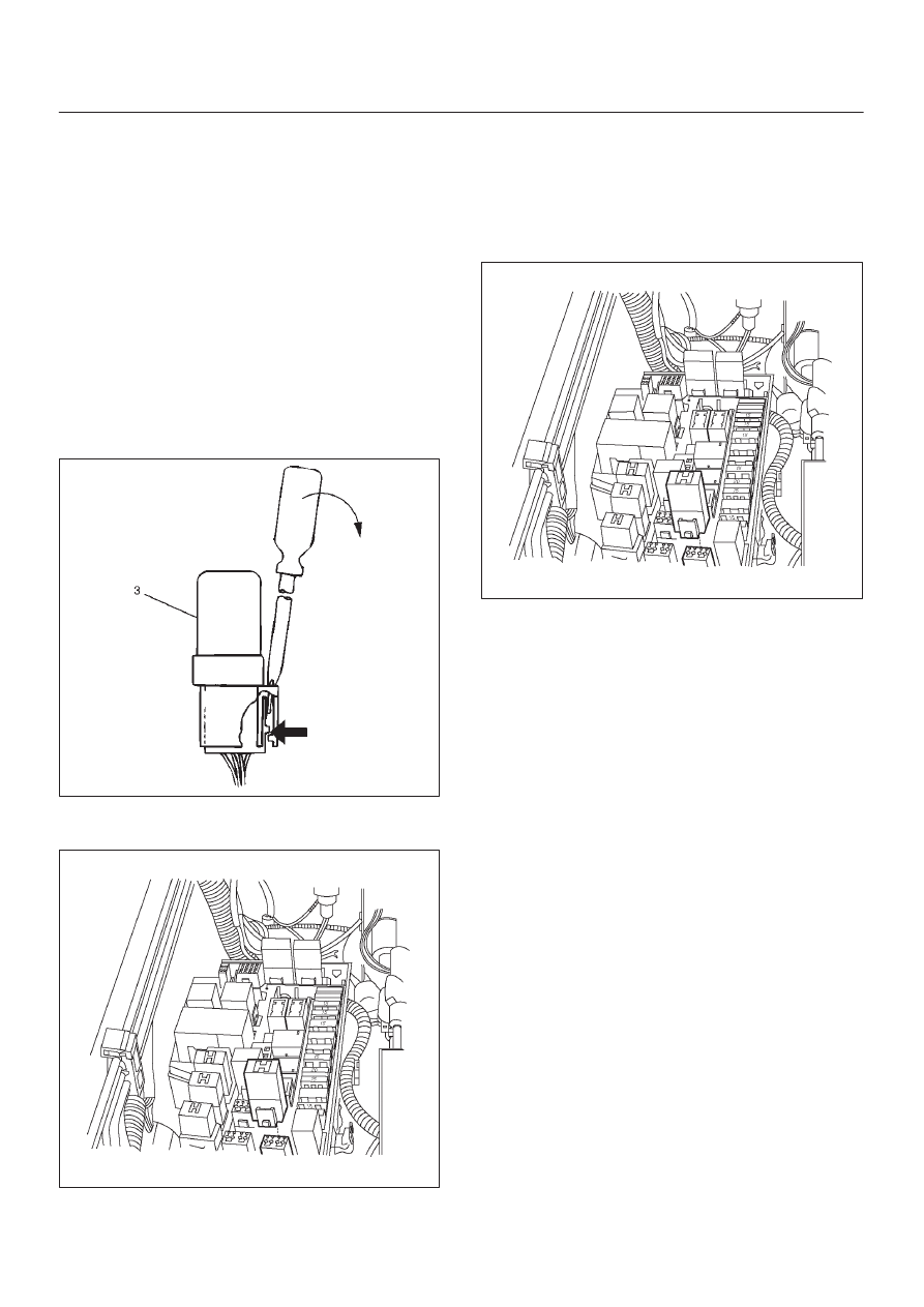
Air Conditioning Thermo Relay
Removal Procedure
1. Remove the fuse and relay box cover from under the
hood.
2. Consult the diagram on the cover to determine which
is the correct relay.
3. Insert a small screwdriver into the catch slot on the
forward side of the fuel pump relay.
D
The screwdriver blade will release the catch inside.
D08RW131
4. Pull the relay straight up and out of the fuse and relay
box.
060R200196
Installation Procedure
1. Insert the relay into the correct place in the fuse and
relay box with the catch slot facing forward.
2. Press down until the catch engages.
D
An audible “click” will be heard.
3. Install the fuse and relay box cover.
060R200196
EVAP Canister Hoses
Service Information
To view the routing of the EVAP canister hoses, refer to
Vehicle Emission Control Information in Diagnosis. Use
6148M or equivalent when you replace the EVAP canister
hoses.
6E–511
6VE1 3.5L ENGINE DRIVEABILITY AND EMISSIONS
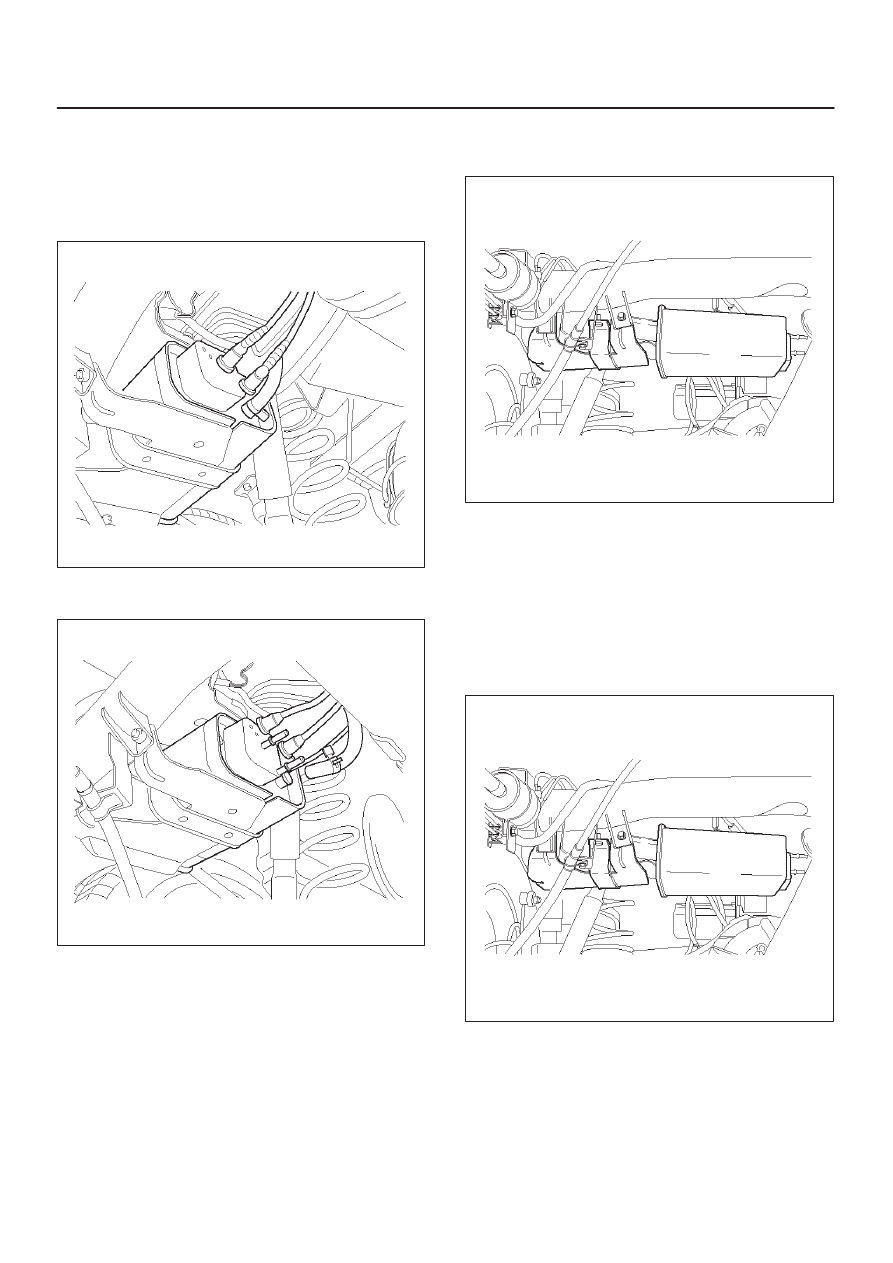
EVAP Canister
Removal Procedure
1. Disconnect the negative battery cable.
2. Disconnect the three hoses from the EVAP canister.
014RW145
3. Disconnect the fuel vapor connector and the purge
hose from the EVAP canister vent solenoid.
014RW147
4. Remove the retaining two bolts on the mounting
bracket and slide the canister out of mounting
bracket.
014RW146
Inspection Procedure
1. Inspect the hoses for cracks and leaks.
2. Inspect the canister for a damaged case.
Installation Procedure
1. Slide the canister into mounting bracket and install
the mounting bracket two bolts.
014RW146
Нет комментариевНе стесняйтесь поделиться с нами вашим ценным мнением.
Текст