Opel Frontera UBS. Service manual — part 1363

6E–46
4JX1–TC ENGINE DRIVEABILITY AND EMISSIONS
No Malfunction Indicator Lamp (MIL)
(Cont'd)
Step
No
Yes
Value(s)
Action
15
Locate and repair the short to ground in the ECM
ignition feed circuit or ECM battery feed circuit.
Is the action complete?
—
Verify repair
—
16
Locate and repair the short to ground in the ignition
feed circuit to the instrument cluster, and replace the
fuse.
Is the action complete?
—
Verify repair
—
17
Replace the ECM (Refer to the Data Programming in
Case of ECM change).
Is the action complete?
—
Verify repair
—
18
Check the MIL driver circuit for a poor connection at the
instrument panel connector.
Was a problem found?
—
Verify repair
Go to
Instrument
Panel in
Electrical
Diagnosis
6E–47
4JX1–TC ENGINE DRIVEABILITY AND EMISSIONS
Malfunction Indicator Lamp (MIL) “ON” Steady
060RW136
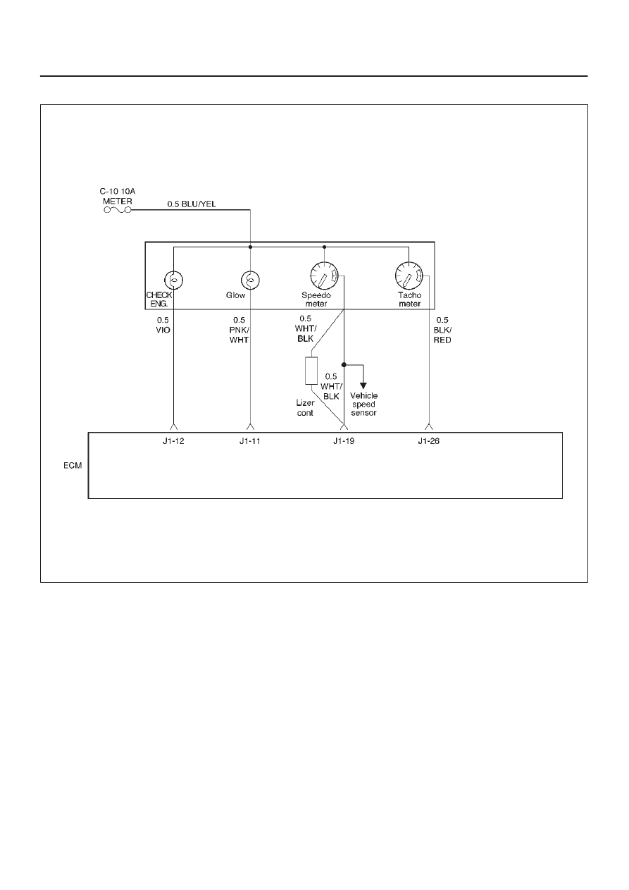
Circuit description
The “Check Engine” lamp (MIL) should always be
illuminated and steady with ignition “ON” and the engine
stopped. Ignition feed voltage is supplied directly to the
MIL indicator. The Engine Control Module ECM turns the
MIL “ON” by grounding the MIL driver circuit.
The MIL should not remain “ON” with the engine running
and no DTC(s) set. A steady MIL with the engine running
and no DTC(s) suggests a short to ground in the MIL
driver circuit.
Diagnostic Aids
An intermittent may be caused by a poor connection,
rubbed–through wire insulation, or a wire broken inside
the insulation. Check for the following items:
D
Poor connection or damaged harness – Inspect the
ECM harness and connectors for improper mating,
broken locks, improperly formed or damaged
terminals, poor terminal-to-wire connection, and
damaged harness.
Test Description
Number(s) below refer to the step number(s) on the
Diagnostic Chart.
2. If the MIL does not remain “ON” when the ECM is
disconnected, the MIL driver wiring is not faulty.
3. If the MIL driver circuit is OK, the instrument panel
cluster is faulty.

6E–48
4JX1–TC ENGINE DRIVEABILITY AND EMISSIONS
Malfunction Indicator Lamp (MIL) “ON” Steady
Step
Action
Value(s)
Yes
No
1
Was the “On-Board diagnostic (OBD) System Check”
performed?
—
Go to
Step 2
Go to
OBD
System
Check
2
1. Ignition “OFF,” disconnect ECM.
2. Ignition “ON,” observe the MIL (CHECK ENGINE
lamp).
Is the MIL “ON?”
—
Go to
Step 3
Go to
Step 5
3
1. Ignition “OFF,” disconnect the instrument panel
cluster.
2. Check the MIL driver circuit between the ECM and
the instrument panel cluster for a short to ground.
3. If a problem is found, repair as necessary.
Was the MIL driver circuit shorted to ground?
—
Go to
OBD
System
Check
Go to
Step 4
4
Replace the instrument panel cluster.
Is the action complete?
—
Go to
OBD
System
Check
—
5
1. Ignition “OFF,” reconnect the ECM.
2. Ignition “ON,” reprogram the ECM. Refer to
On-Vehicle Service in Engine Control Module and
Sensor for procedures.
3. Using the Tech 2 output controls function, select
MIL dash lamp control and command the MIL
“OFF.”
Did the MIL turn “OFF?”
—
Go to
OBD
System
Check
Go to
Step 6
6
Replace the ECM (Refer to the Data Programming in
Case of ECM change).
Is the action complete?
—
Go to
OBD
System
Check
—

6E–49
4JX1–TC ENGINE DRIVEABILITY AND EMISSIONS
Engine Cranks But Will Not Run
Circuit Description
In this type of injector system, the Engine Control Module
(ECM) triggers the correct driver inside the injector, which
then triggers the correct injector based on the 57X signal
received from the crankshaft position sensor (CKP).
During crank, the ECM monitors the CKP 57X signal. The
CKP signal is used to determine which cylinder will fire
first. After the CKP 57X signal has been processed by the
ECM, it will command all four injectors to allow a priming
shot of fuel for all the cylinders. After the priming, the
injectors are left “OFF” during the next four 57X reference
pulses from the CKP. This allows each cylinder a chance
to use the fuel from the priming shot. During this waiting
period, a camshaft position (CMP) signal pulse will have
been received by the ECM. The CMP signal allows the
ECM to operate the injectors sequentially based on
camshaft position. If the camshaft position signal is not
present at start-up, the ECM will begin sequential fuel
delivery with a 1-in-4 chance that fuel delivery is correct.
The engine will run without a CMP signal, but will set a
DTC code.
Diagnostic Aids
An intermittent problem may be caused by a poor
connection, rubbed-through wire insulation or a wire
broken inside the insulation. Check for the following
items:
D
Poor connection or damaged harness – Inspect the
ECM harness and connectors for improper mating,
broken locks, improperly formed or damaged
terminals, poor terminal-to-wore connection, and
damaged harness.
D
Faulty engine coolant temperature sensor – Using a
Tech 2, compare engine coolant temperature with
manifold air temperature on a completely cool engine.
Test Description
Number(s) below refer to the step number(s) on the
Diagnostic Chart.
4. An obvious cause of low fuel pressure would be an
empty fuel tank.
5. The engine will easily start and run if a few injectors
are disabled. It is not necessary to test all injectors
at this time since this step is only a test to verify that
all of the injectors have not been disabled by fuel
contamination.
8.If there is an open or shorted driver circuit, DTCs
0201-0204 should be set.
Engine Cranks But Will Not Run
Step
Action
Value(s)
Yes
No
1
Was the “On-Board Diagnostic (OBD) System Check”
performed?
—
Go to
Step 2
Go to
OBD
System
Check
2
Check the 15 A injector fuse, the 15 A engine device
fuse, and the 15A ECM fuse.
Was a fuse blown?
—
Go to
Step 3
Go to
Step 4
3
Check for a short to ground and replace the fuse.
Is the action complete?
—
Verify repair
—
4
Is fuel tank empty?
—
Fill the fuel
tank
Go to
Step 5
5
Is the right fuel using?
—
Go to
Step 6
Replace the
fuel
6
Is the right engine oil using?
—
Go to
Step 7
Replace the
engine oil
7
Using the Tech–2.
Is DTC P0192 or P0193 set? (Check rail pressure
system)
—
Go to
DTC
P0192 or
DTC P0193
Go to
Step 8
8
Using the Tech–2.
Is DTC P0201 – P0204 set? (Check inject circuit fault)
—
Go to
DTC
P0201 –
P0204
Go to
Step 9
9
Using the Tech–2.
Is DTC P1657 set? (Check ECM Main relay)
—
Go to
DTC
P1657
Go to
Step 10
Нет комментариевНе стесняйтесь поделиться с нами вашим ценным мнением.
Текст