Opel Frontera UBS. Service manual — part 1364

6E–50
4JX1–TC ENGINE DRIVEABILITY AND EMISSIONS
Engine Cranks But Will Not Run
(Cont'd)
Step
No
Yes
Value(s)
Action
10
Refer to
Engine Mechanical Diagnosis to diagnose the
following conditions:
D
Faulty camshaft drive belts
D
Leaking or sticky valves or rings
D
Excessive valve deposits
D
Weak valve springs
D
Incorrect valve timing
D
Leaking head gasket
Is the action complete?
—
Verify repair
Go to
Step 11
11
Observe the “Engine Speed” data display on the Tech 2
while cranking the engine.
Is the engine RPM indicated? (If the Tech 2 is normally
powered from the cigarette lighter socket, and if the
Tech 2 display goes blank while cranking the engine, it
will be necessary to power the Tech 2 directly from the
vehicle battery.)
—
Go to
Step 12
Go to
Step 17
12
1. At the ECM (female) side of the connector
mentioned in step, connect a test light between the
ignition + terminal and one of the injector driver
circuits at the same connector.
2. Ignition “ON.”
3. Observe the test light, and repeat the test for each
injector driver circuit by oscilloscope.
Did the test light stay on when checking any of the 4
injector driver circuits?
—
Go to
Step 13
Go to
Step 15
13
1. Ignition “OFF,” disconnect the ECM.
2. Ignition “ON,” observe the test light.
Is the test light “ON?”
—
Go to
Step 14
Go to
Step 16
14
Locate and repair the short to ground in the injector
driver circuit.
Is the action complete?
—
Verify repair
—
15
Check for an open injector driver circuit.
Was a problem found?
—
Verify repair
Go to
Step 16
16
Replace the ECM (Refer to the Data Programming in
Case of ECM change).
Is the action complete?
—
Verify repair
—
17
1. Raise the vehicle and disconnect the CKP sensor
harness.
2. Ignition “ON.”
3. With a test light to ground, probe the harness
ignition feed terminal.
Did the light illuminate?
—
Go to
Step 19
Go to
Step 18
18
Check the ignition feed wire between the sensor and
the ECM for a short to ground or open circuit.
Is the action complete?
—
Verify repair
—

6E–51
4JX1–TC ENGINE DRIVEABILITY AND EMISSIONS
Engine Cranks But Will Not Run
(Cont'd)
Step
No
Yes
Value(s)
Action
19
1. Ignition “ON.”
2. At the CKP harness connector, connect a test light
between the ignition and ground terminals.
Did the light illuminate?
—
Go to
Step 21
Go to
Step 20
20
Check the sensor ground circuit for an open or short to
voltage.
Is the action complete?
—
Verify repair
—
21
Check the signal circuit between the sensor and the
ECM for a short to ground, short to voltage, or an open.
Was a problem found?
—
Verify repair
Go to
Step 22
22
Replace the CKP sensor.
Is the action complete?
—
Verify repair
Go to
Step 16
6E–52
4JX1–TC ENGINE DRIVEABILITY AND EMISSIONS
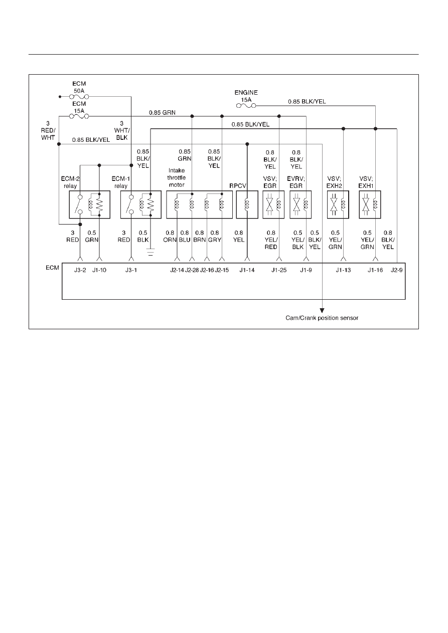
Exhaust Gas Recirculation (EGR) System Check
060RW135
Circuit Description
Introducing exhaust gas into the combustion chamber
lowers combustion temperatures and reduces the
formation of oxides of nitrogen (NOx) in the exhaust gas.
Lower combustion temperatures also prevent detonation.
Diagnostic Aids
The EGR valve chart is a check of the EGR system. An
EGR pintle constantly in the closed position could cause
detonation and high emissions of NOx. An EGR pintle
constantly in the open position would cause a rough idle.

6E–53
4JX1–TC ENGINE DRIVEABILITY AND EMISSIONS
System Check
Step
Action
Value(s)
Yes
No
1
Move the valve up and down to check the slide
resistance.
Is the slide resistance large?
—
Go to
Step 8
Go to
Step 2
2
1. Set the transmission at “Park” or “Neutral”.
2. Put the engine in warming-up operation by idling.
(The engine temperature should be 80
°
C or more)
3. Disconnect the vacuum hose from the EGR valve.
4. Apply a vacuum of 250 mmHg to the EGR valve by
the vacuum pump (mighty pack).
Does the vibration due to engine operation become
larger?
—
Go to
Step 3
Go to
Step 9
3
1. Check if there is not any damage on the vacuum
hose from the vacuum pump to the EGR valve.
2. Install the vacuum pump (mighty pack) to the EGR
valve.
Does the vacuum became 250 mmHg or more at that
time?
250 mmHg or
more
Go to
Step 4
Go to
Step 8
4
Install the EGR valve and the vacuum hose formally
and increase the engine revolution speed to 3000 rpm.
Can both EGR valve 1 and EGR valve 2 be opened and
closed?
—
The system is
normal
Go to
Step 5
5
Measure the resistance of the VSV: EGR coil.
Is the resistance value in the range of 30
W
to 50
W
?
30
∼
50
W
Go to
Step 6
Go to
Step 10
6
Measure the resistance of the EVRV: EGR coil.
Is the resistance value in the range of 10
W
to 13
W
?
10
∼
13
W
Go to
Step 7
Go to
Step 11
7
Was the harness open or poor connection?
—
Go to
Step 12
Go to
Step 13
8
Replace the EGR valve ASM.
Is the action complete?
—
Verify repair
—
9
Clean or replace the EGR valve ASM.
Is the action complete?
—
Verify repair
—
10
Replace the EGR VSV.
Is the action complete?
—
Verify repair
—
11
Replace the EGR EVSV.
Is the action complete?
—
Verify repair
—
12
Repair the harness.
Is the action complete?
—
Verify repair
—
13
Replace the ECM (Refer to the Data Programming in
Case of ECM change).
Is the action complete?
—
Verify repair
—
Нет комментариевНе стесняйтесь поделиться с нами вашим ценным мнением.
Текст