Opel Frontera UBS. Service manual — part 465
6D – 16 ENGINE ELECTRICAL
DIAGNOSIS
GENERAL ON-VEHICLE INSPECTION
The operating condition of the charging system is
indicated by the charge warning lamp. The warning
lamp comes on when the starter swtich is turned to
“ON” position. The charging system operates normally
if the lamp goes off when the engine starts. If the
warning lamp shows abnormality or if undercharged or
overcharged battery condition is suspected, perform
diagnosis by checking the charging system as follows:
Condenser
Generator
Stator Coil
IC Regulator
Starter
SW
Rotor Coil
Battery
P
F
E
B S
L
Relay
B
S
L
QOS
065R200028
1. Check visually the belt and wiring connector.
2. With the engine in stop status, turn the starter
switch to “ON” position and observe the warning
lamp.
1) If lamp does not come on:
Disconnect wiring connector from generator,
and ground terminal “L” on connector side.
2) If lamp comes on:
Repair or replace the generator.
ENGINE ELECTRICAL 6D – 17
UNIT REPAIR
5
4
3
2
1
7
6
10
9
8
11
12
066RW022
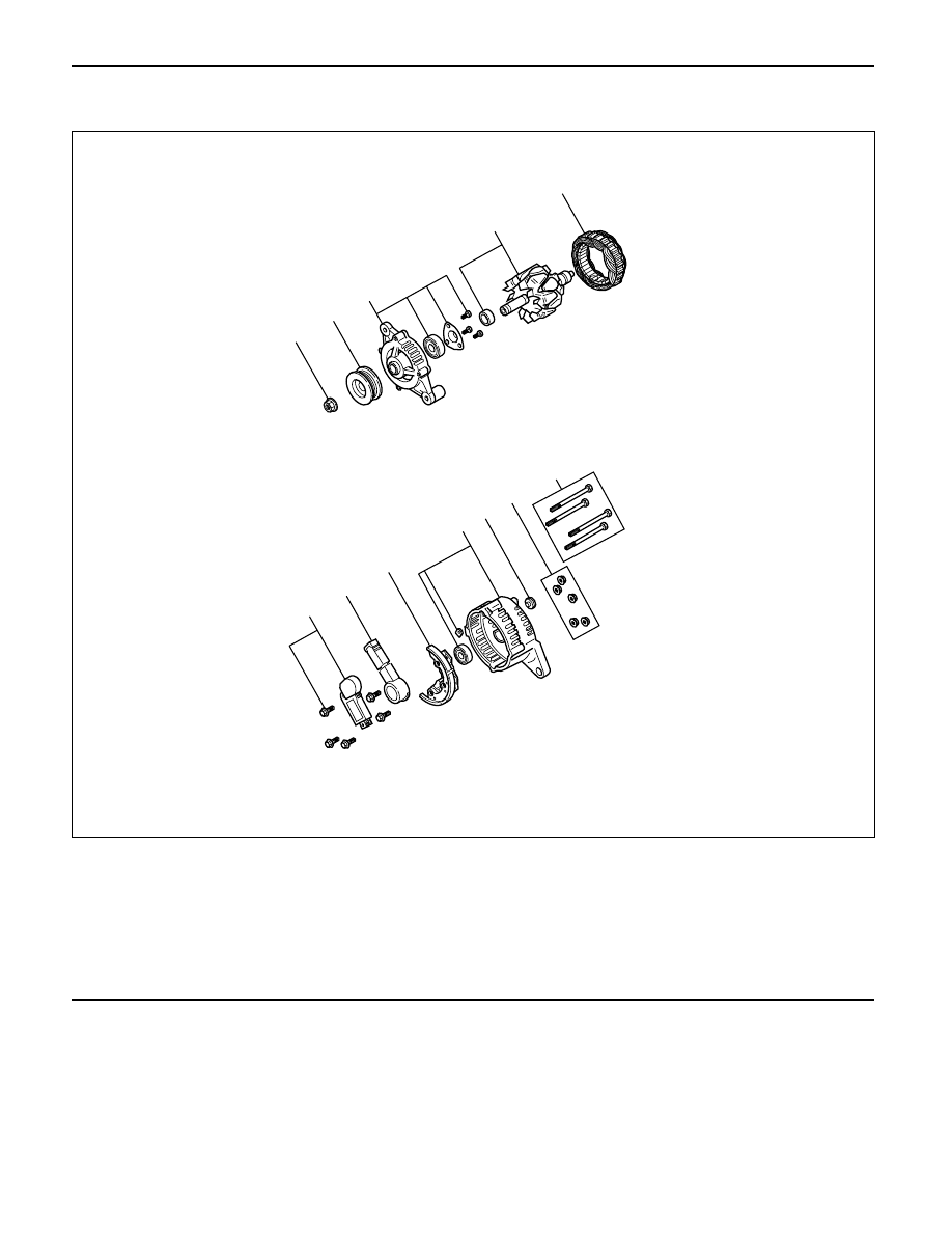
Legend
(1)
Pulley Nut
(2)
Pulley
(3)
Front Cover Assembly
(4)
Rotor Assembly
(5)
Stator Assembly
(6)
Through Bolt
(7)
Nut
(8)
Terminal Insulator Plate
(9)
Rear Cover Assembly
(10)
Diode
(11)
Brush Holder
(12)
Regulator Assembly
6D – 18 ENGINE ELECTRICAL
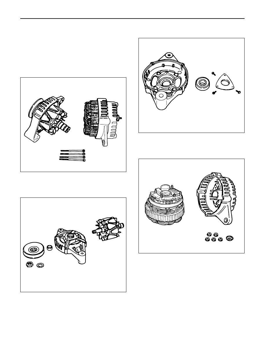
DISASSEMBLY
1. Remove the through bolt.
Insert the tip of a pry bar into the gaps between the
front cover and the stator core.
Pry apart and separate the front cover, rotor, the
rear cover and stator.
NOTE: Take care not to scratch or otherwise damage
the stator coil with pry bar.
2. Clamp the rotor in a vise and then remove the nut
and pulley.
3. Remove the rotor assembly from front cover.
4. Remove screws with bearing retainer from front
cover and remove bearing.
5. Remove the mounting nuts holding the “B ”
terminal, the diode, and the brush holder.
6. Separate the rear cover from the stator.
F06RT021
F06RT022
F06RT023
F06RT024
ENGINE ELECTRICAL 6D – 19
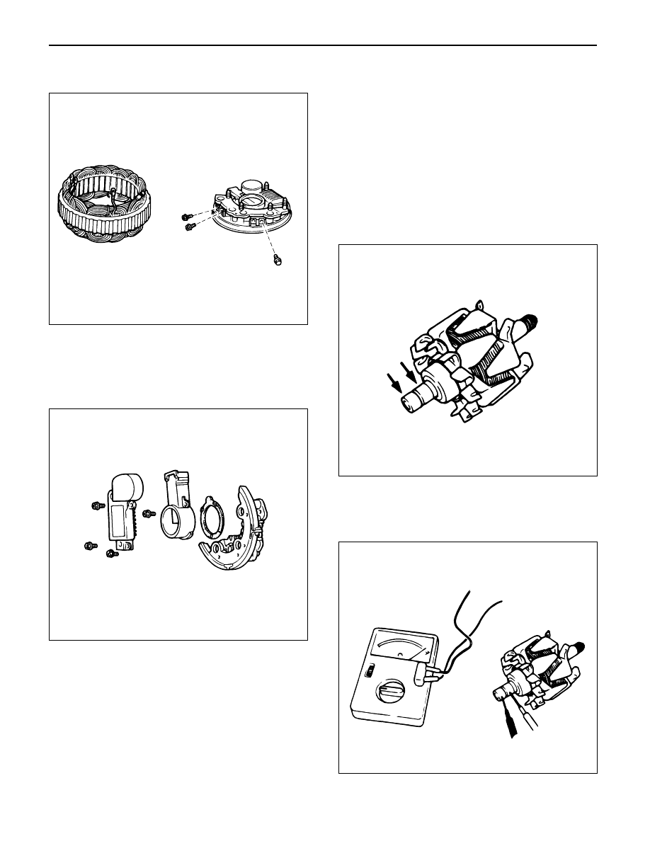
7. Remove bolts which secure stator terminal to
rectifier terminal, and remove stator.
8. Remove Bolts which secure regulator, rectifier and
brush-holder, and separate these parts.
NOTE: Do not apply a shock or load to regulator,
rectifier and brush holder.
INSPECTION AND REPAIR
Repair or replace necessary parts if extreme wear or
damage is found during inspection.
Rotor Assembly
1. Check the face of the slip rings for contamination
and roughness. If found to be scored, dress with a
fine sandpaper (#500 – 600). If found to be
contaminated, clean with a cloth saturated with
alcohol.
2. Measure the outside diameter of the slip rings.
Standard: 27 mm (1.06 in)
Limit: 26 mm (1.02 in)
3. Check resistance between slip rings, and replace if
there is no continuity.
Standard: 3.75
Ω
or less
066RS030
066RW025
066RS032
066RS033
Нет комментариевНе стесняйтесь поделиться с нами вашим ценным мнением.
Текст