Opel Frontera UBS. Service manual — part 163
4C–9
DRIVE SHAFT SYSTEM
Front Hub and Disc (with Shift on the Fly)
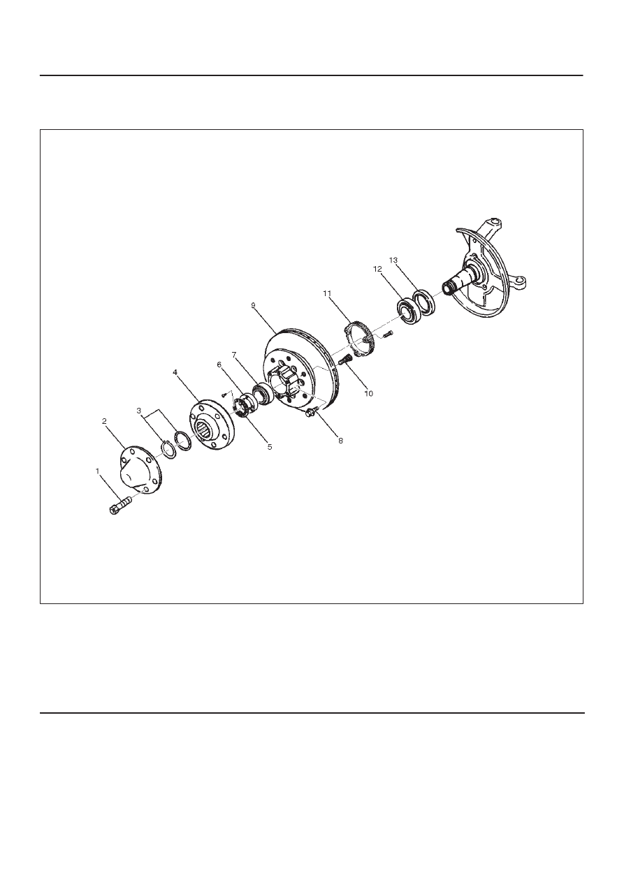
Disassembled View
411RW001
Legend
(1) Bolt
(2) Cap
(3) Snap Ring and Shim
(4) Hub Flange
(5) Lock Washer and Lock Screw
(6) Hub Nut
(7) Outer Bearing
(8) Bolt
(9) Hub and Disc Assembly
(10) Wheel Pin
(11) ABS Sensor Ring (If equipped)
(12) Inner Bearing
(13) Oil Seal
Disassembly
1. Before disassembly, select the 2WD position.
2. Jack up the front of vehicle and support frame with
jack stands.
3. Remove the disc brake caliper assembly and hang it
on the frame with wires. Refer to Front Disc Brake
Caliper Assembly in Brakes section.
4. Remove bolt.
5. Remove cap.
6. Remove snap ring and shim.
7. Remove hub flange.
4C–10
DRIVE SHAFT SYSTEM
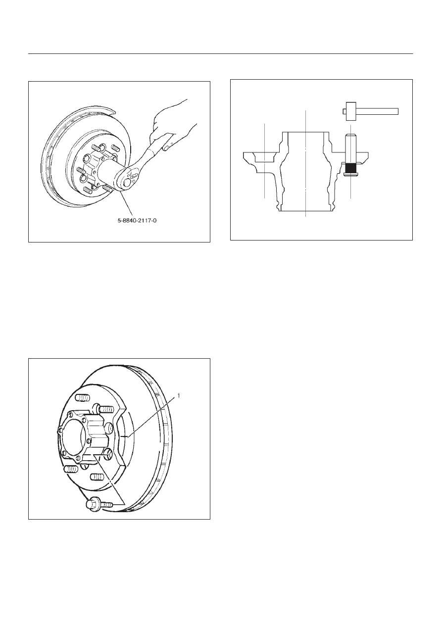
8. Remove lock washer and lock screw.
9. Use wrench 5–8840–2117–0, remove hub nut.
411RW005
10. Remove hub and disc assembly.
11. Remove ABS sensor ring (If equipped).
12. Remove outer bearing.
13. Remove oil seal.
14. Remove inner bearing.
15. Remove bolt , if necessary, replace the wheel pin in
the following manner.
D
Apply a scribe mark(1) to disc to hub.
D
Clamp the hub and disc assembly in a vise, using
protective pads. Remove the 6 disc–to–hub
retaining bolts.
411RS003
D
Place hub on a suitable work surface and remove
the studs by using a hammer.
411RS004
Inspection and Repair
Make necessary correction or parts replacement if wear,
damage, corrosion or any other abnormal conditions are
found through inspection.
Check the following parts:
D
Hub
D
Hub bearing oil seal
D
Knuckle spindle
D
Disc
D
Caliper
D
Shift on the fly system parts (Cap, Hub flange, Shim,
Snap ring)
D
ABS sensor ring (If equipped)
For inspection and servicing of disc caliper and related
parts, refer to Brakes section.
4C–11
DRIVE SHAFT SYSTEM
Reassembly
1. Install wheel pin.
D
Place the hub on a wood workbench or a block of
wood approx. 6” by 6” to protect the wheel stud
ends and threads.
D
Insert a wheel stud using a hammer.
Be sure the wheel stud is started squarely and
seats completely.
411RS005
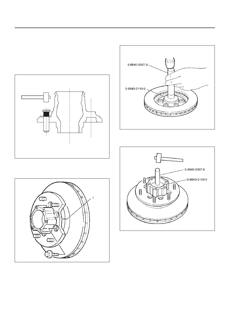
2. Align scribe marks(1) and attach the hub to the disc,
then tighten the bolts to the specified torque.
Torque: 103 N·m (10.5 kg·m/76 lb ft)
411RS003
3. Use installer 5–8840–2119–0 and grip
5–8840–0007–0, then install the inner bearing by
driving it into the hub.
411RW006
4. Use installer 5–8840–2118–0 and grip
5–8840–0007–0, then install the outer bearing by
driving it into the hub.
411RW007
4C–12
DRIVE SHAFT SYSTEM
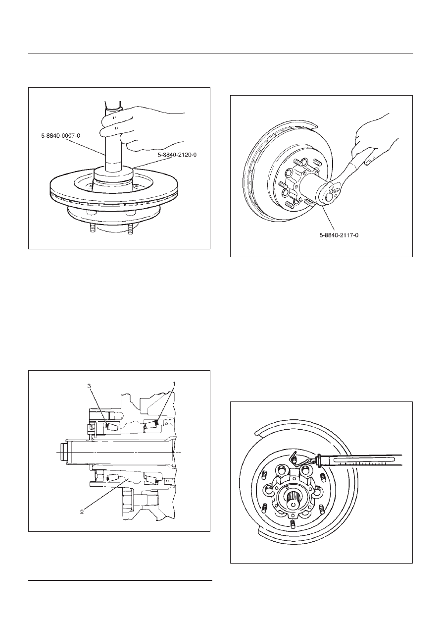
5. Apply grease (NLGI No.2 or equivalent) to the lip
portion, then install oil seal by using installer
5–8840–2120–0 and grip 5–8840–0007–0.
411RW008
6. Install ABS sensor ring, then tighten the bolts to the
specified torque.
Torque: 18 N·m (1.8 kg·m/13 lb ft)
7. Install hub and disc assembly.
D
Apply grease in the hub.
D
Apply wheel bearing type grease NLGI No. 2 or
equivalent to the outer and inner bearing.
Grease Amount
Hub: 35 g (1.23 oz)
Outer bearing: 10 g (0.35 oz)
Inner bearing: 15 g (0.53 oz)
411RS009
Legend
(1) Inner Bearing
(2) Hub
(3) Outer Bearing
8. Install hub nut. Turn the place where there is a
chamfer in the tapped hole to the outer side, then
attach the nut by using front hub nut wrench
5–8840–2117–0.
411RW005
Preload Adjustment
1. Tighten the hub nut to 29 N·m (3.0 kg·m/22 lb ft),
then fully loosen the nut.
2. Tighten the hub nut to the value given below,
using a spring scale on the wheel pin.
New bearing and New oil seal
Bearing Preload: 20 – 25 N (2.0–2.5 kg/4.4 –
5.5 lb)
Used bearing and New oil seal
Bearing Preload: 12 – 18 N (1.2–1.8 kg/2.6 –
4.0 lb)
If the measured bearing preload is outside the
specifications, adjust it by loosening or tightening the
bearing nut.
411RS011
Нет комментариевНе стесняйтесь поделиться с нами вашим ценным мнением.
Текст