Opel Frontera UBS. Service manual — part 164
4C–13
DRIVE SHAFT SYSTEM
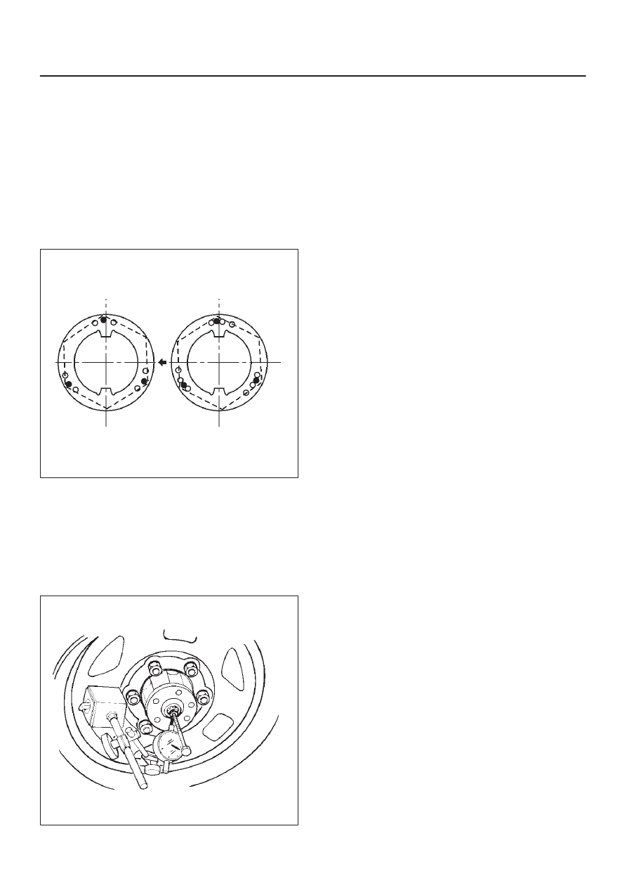
9. Install lock washer and lock screw in the following
manner.
D
Turn the side with larger diameter of the tapered
bore to the vehicle outer side, then attach the
washer.
D
If the bolt holes in the lock plate are not aligned with
the corresponding holes in the nut, reverse the lock
plate.
D
If the bolt holes are still out of alignment, turn in the
nut just enough to obtain alignment.
D
Screw is to be fastened tightly so its head may
come lower than the surface of the washer.
411RS012
10. Apply adhesive (LOCTITE 515 or equivalent) to both
joining flange faces then install hub flange.
11. Install snap ring and shim.
D
Adjust the clearance between the free wheeling hub
body and the snap ring.
Clearance: 0 mm–0.3 mm (0 in–0.012 in)
Shims Available: 0.2 mm, 0.3 mm, 0.5 mm,
1.0 mm (0.008 in, 0.012 in, 0.020 in, 0.039 in)
411RW002
12. Install hub cap.
13. Tighten the bolts to the specified torque.
Torque: 59 N·m (6.0 kg·m/43 lb ft)
4C–14
DRIVE SHAFT SYSTEM
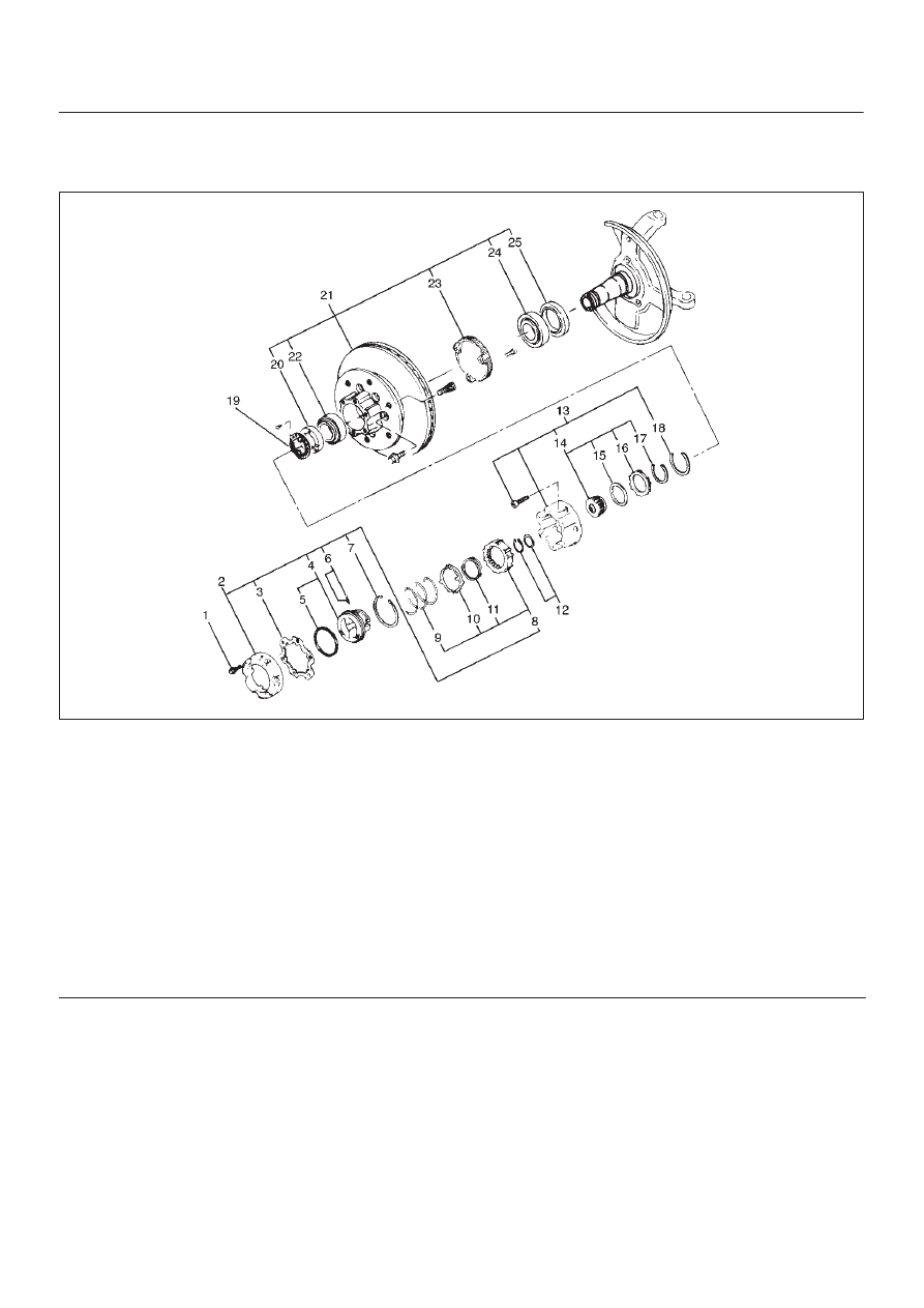
Front Hub and Disc with Manual Locking Hub
Disassembled View
411RW009
Legend
(1) Bolt
(2) Cover Assembly
(3) Gasket
(4) Knob
(5) X–ring
(6) Detent Ball and Spring
(7) Snap Ring
(8) Clutch Assembly
(9) Compression Spring
(10) Follower
(11) Retaining Spring
(12) Snap Ring and Shim
(13) Body Assembly
(14) Inner Assembly
(15) Spacer
(16) Ring
(17) Snap Ring
(18) Snap Ring
(19) Lock Washer and Lock Screw
(20) Hub Nut
(21) Hub and Disc Assembly
(22) Outer Bearing Outer Race
(23) ABS Sensor Ring (if so equipped)
(24) Inner Bearing Outer Race
(25) Oil Seal
Disassembly
1. Before disassembly, jack up the front of vehicle and
support frame with jack stands.
2. Remove the disc brake caliper assembly and hang it
on the frame with wires. Refer to Front Disk Brake
Caliper Assembly in Brakes section.
4C–15
DRIVE SHAFT SYSTEM
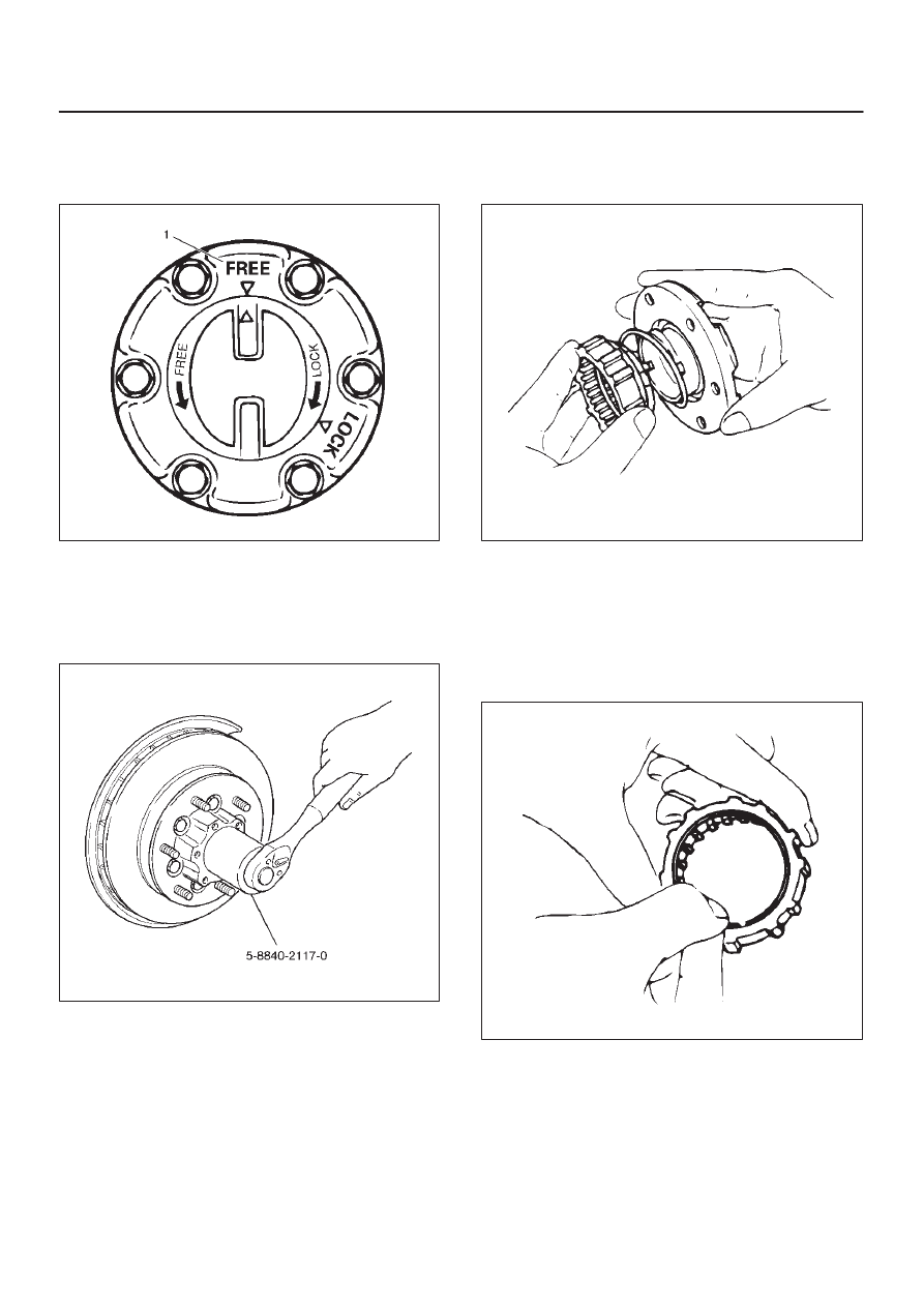
3. Remove bolt.
Before removal, shift transfer lever into “2H” position,
set free wheeling hub knob into “FREE” position (1),
and run the vehicle about 50m (160 ft).
411RW010
4. Remove cover assembly.
5. Remove snap ring and shim.
6. Remove body assembly.
7. Remove lock washer and lock screw.
8. Remove hub nut by using wrench 5–8840–2117–0.
411RW005
9. Remove hub and disc assembly.
10. Remove ABS sensor ring (If equipped).
11. Remove outer bearing outer race.
12. Remove oil seal.
13. Remove inner bearing outer race.
14. While pushing follower knob against cover, turn clutch
assembly clockwise and then remove clutch
assembly from knob.
411RW011
15. Remove gasket.
16. Remove snap ring.
17. Remove knob.
18. Remove compression spring.
19. Remove follower.
20. Remove retaining spring from clutch assembly by
turning it counterclockwise.
411RW012
21. Remove dedent ball and spring.
22. Remove X–ring.
23. Remove snap ring.
24. Remove inner assembly.
25. Remove snap ring.
26. Remove ring.
27. Remove spacer.
4C–16
DRIVE SHAFT SYSTEM
Inspection and Repair
Make necessary correction or parts replacement if wear,
damage, corrosion or any other abnormal condition are
found through inspection.
Check the following parts.
D
Hub
D
Hub bearing, oil seal
D
Knuckle spindle
D
Disc
D
Caliper
D
Free wheeling hub parts (Clutch, knob, follower,
inner, ring and spring)
D
ABS sensor ring (if so equipped)
For inspection and servicing of disc caliper, and relative
parts, refer to Brakes section.
Reassembly
1. Install spacer.
Apply about 1 g wheel bearing grease to both face of
spacer.
2. Install ring.
Apply about 3 g wheel bearing grease to inside face
of ring.
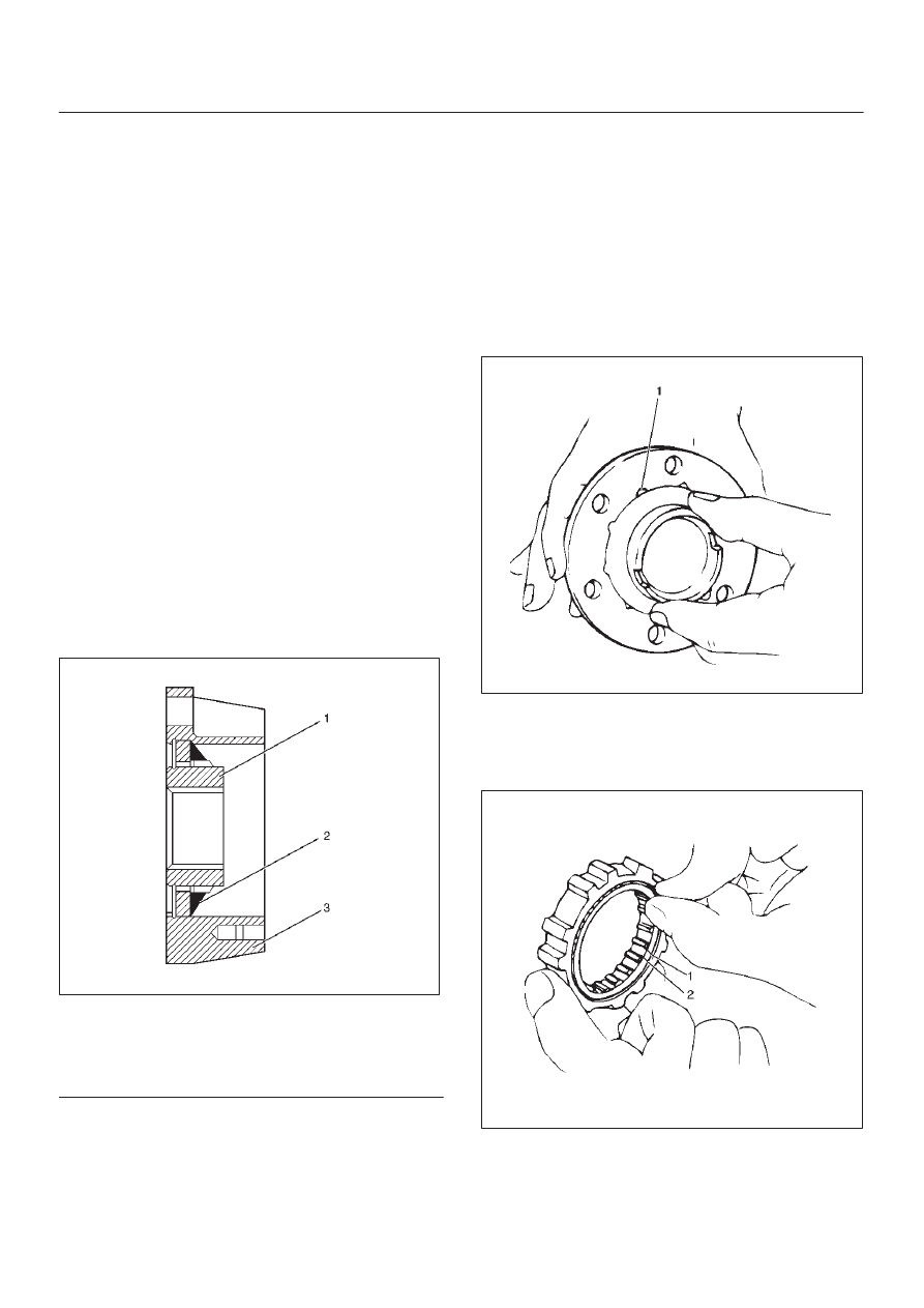
3. Install snap ring
Assembly with grease surplus being left unwiped up
as illustrated.
411RW013
Legend
(1) Inner Assembly
(2) Apply Grease
(3) Body
4. Install inner assembly.
Apply grease to splined portion of body.
5. Install snap ring.
6. Install X–ring.
Apply wheel bearing grease to hub lock ring and fit it
in knob paying attention to mounting direction.
NOTE: After fitting, make sure that the hub lock ring is not
twisted.
7. Apply wheel bearing grease to ball and spring and fit
them in knob.
8. Install knob.
1. Apply grease to outer circumference of knob and
inner circumference of cover.
2. Align detent ball (1) to a groove cut in the cover.
411RW014
9. Install snap ring.
Turn the smoother face to knob side.
10. Align the end of retaining spring (1) with clutch spring
groove (2) and fit in the spring.
411RW015
Нет комментариевНе стесняйтесь поделиться с нами вашим ценным мнением.
Текст