Opel Frontera UBS. Service manual — part 2596
TRANSMISSION CONTROL SYSTEM (4L30–E)
7A1–35
DTC P0706 Transmission Range Switch (Mode Switch) Performance
D07RW031
Circuit Description
D
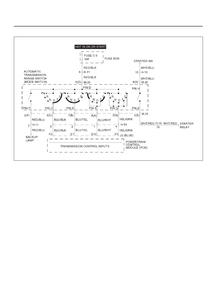
The range switch supplies the Powertrain Control
Module (PCM) with information regarding the selector
lever position: P, R, N, D, 3, 2 or L. The selector lever
position is indicated by the state of four ON/OFF
contracts. The range switch is located on one side of
the transmission. It is on the transmission manual
shaft and is fixed to the main case.
D
The range switch is also used to provide the
information P or N to the engine crank wiring. The
engine can be cranked only if connector M–25
terminal 4(H) is connected to terminal 1(E) which is
connected to ground.
D
The range switch is also used to provide the backup
lamp power in reverse. This is why the mode switch is
supplied through a 10A fuse (C–3). This fuse can
burn due to a shot circuit in the backup lamp.
D
This DTC detects an invalid state of the range switch
or the range switch circuit by deciphering the range
switch inputs. This is a type “D” DTC.
Conditions For Setting The DTC
This DTC will set if any of the following conditions occurs:
Condition 1 (“R” bad position):
D
Engine is running.
D
No output speed DTCP0722, P0723.
D
Output speed greater than 3,200 RPM.
D
Range switch indicates “R”.
D
All conditions met for 4 seconds.
Condition 2 (“P” or “N” bad position):
D
Engine is running.
D
No TPS codes.
D
Engine speed is less than 3,000 RPM.
D
TP angle is greater than 20%.
D
Range switch indicates “P” or “N”.
D
All conditions met for 4 seconds.
Action Taken When The DTC Sets
D
Default to “D” position.
D
The PCM will not illuminate the CHECK TRANS
Lamp.
Conditions For Clearing The DTC
D
The DTC can be cleared from the PCM history by
using a scan tool.
D
The DTC will be cleared from history when the vehicle
has achieved 40 warmup cycles without a failure
reported.
D
The PCM will cancel the DTC default actions when
the fault no longer exists and the ignition is cycled “off”
long enough to power down the PCM.

7A1–36 TRANSMISSION CONTROL SYSTEM (4L30–E)
Diagnostic Aids
D
Refer to the accompanying chart for the normal range
signals and the illegal combinations.
D
Inspect the wiring for poor electrical connections at
the PCM and at the transmission 8–way connector.
Look for possible bent, backed out, deformed or
damaged terminals. Check for weak terminal tension
as well. Also check for a chafed wire that could short
to bare metal or other wiring. Inspect for a broken wire
inside the insulation.
D
When diagnosing for a possible intermittent short or
open condition, move the wiring harness while
observing test equipment for a change.
D
Refer to the “Range Switch Logic Table” for further
information.
Test Description
The numbers below refer to the step numbers on the
diagnostic chart:
2. This test checks the indicated range signal to the
manual valve actually selected.
5. This test checks for continuity between each
selected range switch connector terminals.
Range Switch Logic Table
Range
Range Switch Pin
g
Position
A
B
C
P(G)
Park
ON
OFF
OFF
ON
Reverse
ON
ON
OFF
OFF
Neutral
OFF
ON
OFF
ON
D4
OFF
ON
ON
OFF
D3
ON
ON
ON
ON
2
ON
OFF
ON
OFF
L
OFF
OFF
ON
ON
Illegal
OFF
OFF
OFF
OFF
Illegal
OFF
OFF
OFF
ON
DTC P0706 Transmission Range Switch (Mode Switch) Performance
Step
Action
Yes
No
1
Perform the following checks:
D
The transmission linkage from the select lever to the manual
valve is adjusted properly.
D
Diagnostic circuit check.
Were the checks performed?
Go to Step 2
—
2
1. Install the scan tool.
2. With the engine “off”, turn the ignition switch “on”.
NOTE: Before clearing DTC(s), use the scan tool to record “Failure
Records” for reference, as data will be lost when the “Clear Info”
function is used.
3. Record the DTC “Failure Records”.
4. Select each transmission range: DL, D2, D3, D4, N, R, and P.
Does each selected transmission range match the scan tool
“Range Switch” display?
Go to Diagnostic
Aids
Go to Step 3
3
Are all range switch pin displays incorrect?
Go to Step 4
Go to Step 5
4
Check fuse and wiring to the 8–way connector terminal 5(D) for
opens.
Refer to Mode Switch in Automatic Transmission (4L30–E)
section.
If no problem was found, replace the range switch.
Is the replacement complete?
Go to Step 8
—
5
1. Disconnect the 8–way range switch connector.
2. Using ohmmeter, check continuity between terminal 5(D) and
respectively terminals 3(G), 6(C), 7(B) and 8(A) of the 8–way
range switch connector.
3. Move shift selector lever through all positions and compare
results with “Range Switch Logic Table”.
Is one range switch pin display incorrect?
Go to Step 6
Go to Step 7
6
Check the affected wiring and connector, and repair.
Is the repair complete?
Go to Step 8
—

TRANSMISSION CONTROL SYSTEM (4L30–E)
7A1–37
DTC P0706 Transmission Range Switch (Mode Switch) Performance (Cont’d)
Step
No
Yes
Action
7
Check the Powertrain Control Module (PCM) connectors for poor
connection.
If no problem was found, replace the PCM.
Is the replacement complete?
Go to Step 8
—
8
1. After the repair is complete, use the scan tool to select “DTC”,
then “Clear Info” function and road test the vehicle.
2. Review the scan tool “DTC Info”.
Has the last test failed or is the current DTC displayed?
Begin diagnosis
again
Go to Step 1
Repair verified
Exit DTC table
7A1–38 TRANSMISSION CONTROL SYSTEM (4L30–E)
DTC P0712 Transmission Fluid Temperature (TFT) Sensor Circuit Low Input
D07RW029
Circuit Description
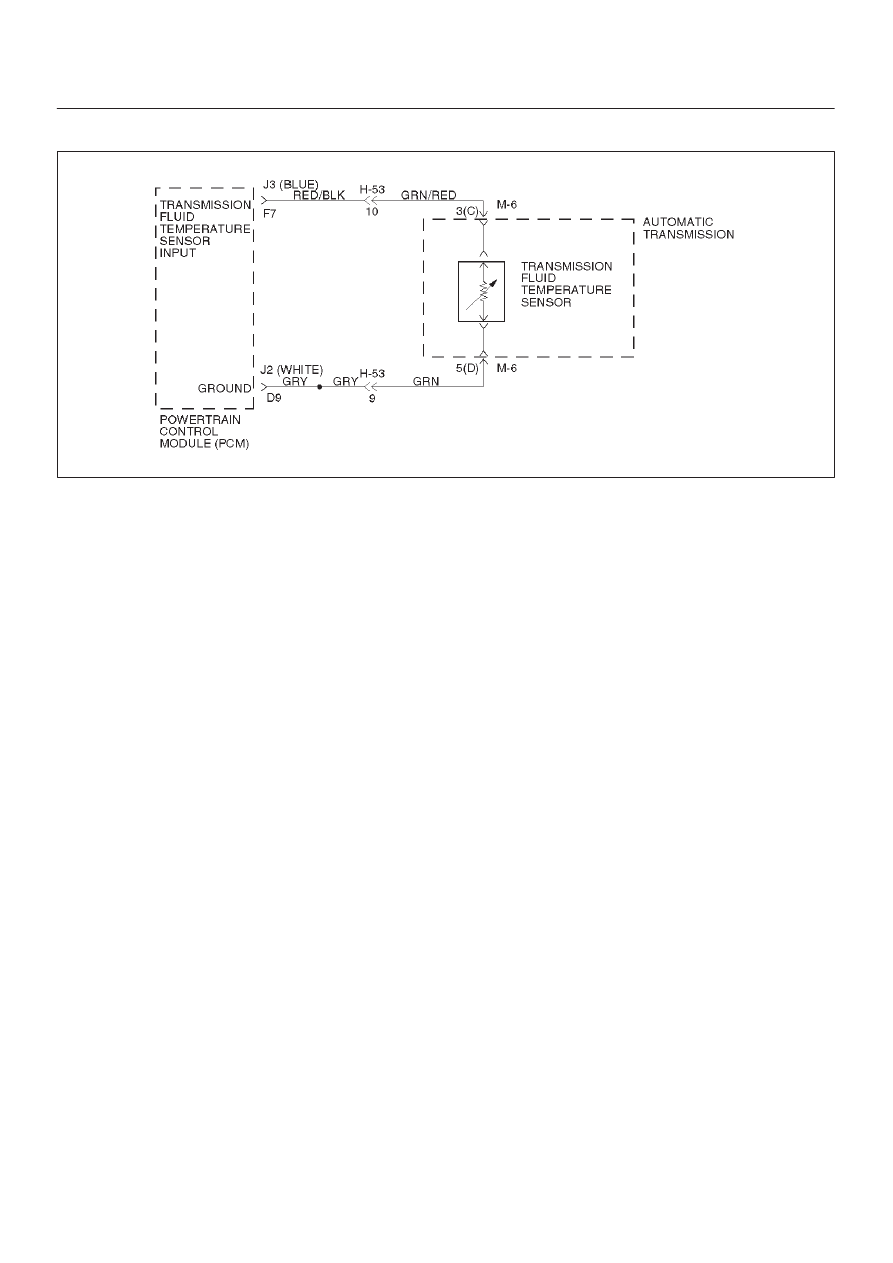
The TFT sensor is a thermister that controls the signal
voltage to the PCM. The PCM supplies a 5–volt reference
signal to the sensor on circuit RED/BLK–GRN/RED.
When the transmission fluid is cold, the sensor resistance
is high. The PCM detects high signal voltage. As the
transmission fluid temperature increases to the normal
operating temperature of 100
°
C (212
°
F), the sensor
resistance becomes less and the voltage decreases to
1.5 to 2 volts. With transmission fluid over temperature
and DTC P0218 also set, check the transmission cooling
system.
This DTC detects a continuous short to ground in the TFT
signal circuit or the TFT sensor. This is a type “D” DTC.
Conditions For Setting The DTC
D
Battery voltage is between 10 and 16 volts.
D
Ignition is “on”.
D
TFT sensor indicating a voltage less than 0.4 volts.
D
All conditions met for 20 seconds.
Action Taken When The DTC Sets
D
Transmission default temperature will be:
80
°
C (176
°
F) if engine temperature code is set.
100
°
C (212
°
F) if engine temperature is warm.
80
°
C (176
°
F) if engine run time is greater than 5
minutes.
21
°
C (69.8
°
F) if engine run time is less than 5
minutes.
D
The PCM will not illuminate the CHECK TRANS
Lamp.
Conditions For Clearing The DTC
D
The DTC can be cleared from the PCM history by
using a scan tool.
D
The DTC will be cleared from history when the vehicle
has achieved 40 warmup cycles without a failure
reported.
D
The PCM will cancel the DTC default actions when
the fault no longer exists and the ignition is cycled “off”
long enough to power down the PCM.
Diagnostic Aids
D
Check harness routing for a potential short to ground
in circuit RED/BLK–GRN/RED. Scan tool TFT
display should rise steadily to about 100
°
C (212
°
F),
then stabilize.
D
Inspect the wiring for poor electrical connection at the
PCM and at the transmission 16–way connector.
Look for possible bent, backed out, deformed or
damaged terminals. Check for weak terminal tension
as well. Also check for a chafed wire that could short
to bare metal or other wiring. Inspect for a broken wire
inside the insulation.
D
When diagnosing for a possible intermittent short or
open condition, move the wiring harness while
observing test equipment for a change.
D
The temperature to resistance value scale may be
used to test the TFT sensor at the various
temperature levels to evaluate the possibility of a
“skewed” (mis–scaled) sensor.
A “skewed” sensor could result in delayed garage
shifts or TCC complaints.
D
Verify customer driving habits, trailer towing, etc.
Test Description
The numbers below refer to the step numbers on the
diagnostic chart:
2. This test checks for a short to ground or a “skewed”
sensor.
3. This test checks for an internal fault within the
transmission by creating an open.
Нет комментариевНе стесняйтесь поделиться с нами вашим ценным мнением.
Текст