Opel Frontera UBS. Service manual — part 2597
TRANSMISSION CONTROL SYSTEM (4L30–E)
7A1–39
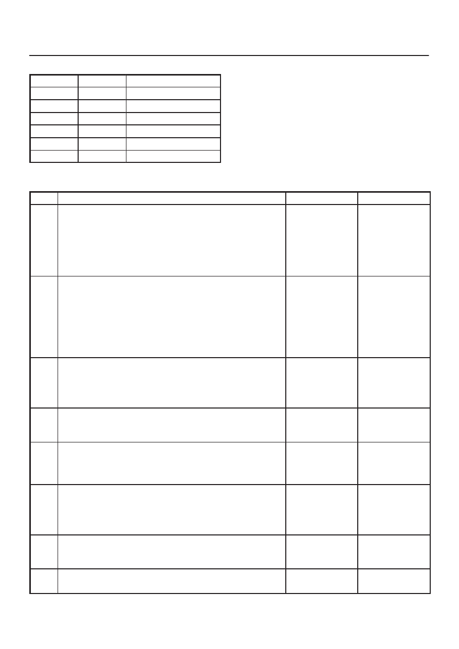
Resistance Chart
°
C
°
F
Resistance (k
W
)
–40
–40
672
0
32
65
20
68
25
80
176
2.5
120
248
0.78
150
304
0.37
DTC P0712 Transmission Fluid Temperature (TFT) Sensor Circuit Low Input
Step
Action
Yes
No
1
Perform the transmission fluid checking procedure. Refer to
Checking Transmission Fluid Level and Condition in Automatic
Transmission (4L30–E) section.
Was the fluid checking procedure performed?
Go to Step 2
Refer to
Checking
Transmission
Fluid Level and
Condition in
Automatic
Transmission
(4L30–E) section
2
1. Install the scan tool.
2. With the engine “off”, turn the ignition switch “on”.
NOTE: Before clearing DTC(s), use the scan tool to record “Failure
Records” for reference, as data will be lost when the “Clear Info”
function is used.
3. Record the DTC “Failure Records”.
Does the scan tool display a TFT sensor signal voltage less than
0.4 volts?
Go to Step 3
Go to Diagnostic
Aids
3
1. Turn the ignition “off”.
2. Disconnect the transmission 16–way connector H–53.
3. Turn the ignition “on”.
Does the TFT signal voltage change to match the voltage 4.92
volts?
Go to Step 4
Go to Step 9
4
Using the J39200 DVOM, measure the resistance between
terminals 3(C) and 5 (D).
Is the resistance within specifications? (See Resistance Chart.)
Go to Diagnostic
Aids
Go to Step 5
5
1. Disconnect the transmission 5–way connector M–6.
2. Using the J39200 DVOM, measure the resistance between
terminals 3(C) and 5(D).
Is the resistance within specifications? (See Resistance Chart.)
Go to Diagnostic
Aids
Go to Step 6
6
1. Remove the transmission oil pan. Refer to Transmission Oil
Temperature Sensor (Adapter Case) in Automatic
Transmission (4L30–E) section.
2. Check the internal wiring harness for a short to ground.
Was a problem found?
Go to Step 8
Go to Step 7
7
1. Disconnect the internal wiring harness at the TFT sensor.
2. Measure the resistance of the TFT sensor.
Is the resistance within specifications? (See Resistance Chart.)
Go to Diagnostic
Aids
Go to Step 8
8
Replace the TFT Sensor.
Is the replacement complete?
Go to Step 12
—

7A1–40 TRANSMISSION CONTROL SYSTEM (4L30–E)
DTC P0712 Transmission Fluid Temperature (TFT) Sensor Circuit Low Input (Cont’d)
Step
No
Yes
Action
9
Check circuit RED/BLK–GRN/RED for a short to ground.
Was a problem found?
Go to Step 12
Go to Step 10
10
Check the PCM for faulty connections.
Was a problem found?
Go to Step 12
Go to Step 11
11
Replace the PCM. Refer to Powertrain Control Module (PCM) in
Automatic Transmission (4L30–E) section.
Is the replacement complete?
Go to Step 12
—
12
1. After the repair is complete, use the scan tool to select “DTC”,
then “Clear Info” function and ensure the following conditions
are met:
TFT sensor indicates a voltage greater than 0.33 volts for 2
seconds.
2. Review the scan tool “DTC info”.
Has the last test failed or is the current DTC displayed?
Begin diagnosis
again
Go to Step 1
Repair verified
Exit DTC table
TRANSMISSION CONTROL SYSTEM (4L30–E)
7A1–41
DTC P0713 Transmission Fluid Temperature (TFT) Sensor Circuit High Input
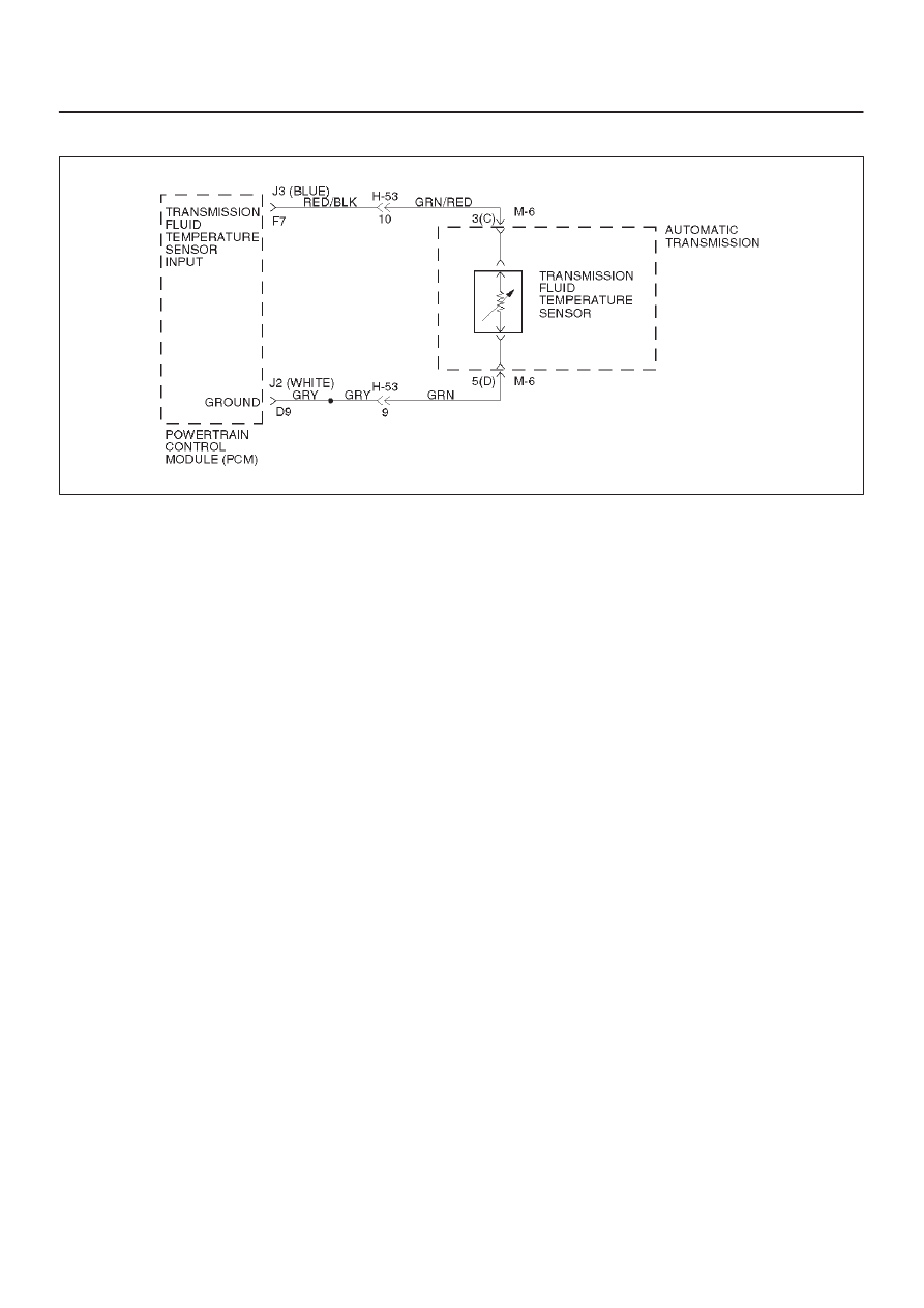
D07RW029
Circuit Description
The TFT sensor is a thermistor that controls the signal
voltage to the PCM. The PCM supplies a 5–volt reference
signal to the sensor on circuit RED/BLK–GRN/RED.
When the transmission fluid is cold, the sensor resistance
is high and the PCM will sense high signal voltage. As the
transmission fluid temperature warms to the normal
operating temperature of 100
°
C (212
°
F), the sensor
resistance becomes less and the voltage decreases to
about 1.5 to 2 volts.
This DTC detects a continuous open or short to power in
the TFT signal circuit or the TFT sensor. This is a type “D”
DTC.
Conditions For Setting The DTC
D
Battery voltage is between 10 and 16 volts.
D
Ignition is “on”.
D
TFT sensor indicating a voltage greater than 4.86
volts.
D
All conditions met for 20 seconds.
Action Taken When The DTC Sets
D
Transmission default temperature will be:
80
°
C (176
°
F) if engine temperature code is set.
100
°
C (212
°
F) if engine temperature is warm.
80
°
C (176
°
F) if engine run time is greater than 5
minutes.
21
°
C (69.8
°
F) if engine run time is less than 5
minutes.
D
The PCM will not illuminate the CHECK TRANS
Lamp.
Conditions For Clearing The DTC
D
The DTC can be cleared from the PCM history by
using a scan tool.
D
The DTC will be cleared from history when the vehicle
has achieved 40 warmup cycles without a failure
reported.
D
The PCM will cancel the DTC default actions when
the fault no longer exists and the ignition is cycled “off”
long enough to power down the PCM.
Diagnostic Aids
D
Inspect the wiring for poor electrical connection at the
PCM and at the transmission 16–way connector.
Look for possible bent, backed out, deformed or
damaged terminals. Check for weak terminal tension
as well. Also check for a chafed wire that could short
to bare metal or other wiring. Inspect for a broken wire
inside the insulation.
D
When diagnosing for a possible intermittent short or
open condition, move the wiring harness while
observing test equipment for a change.
D
Scan tool displays transmission fluid temperature in
degrees. After transmission is operating, the
temperature should rise steadily to about 100
°
C
(212
°
F), then stabilize.
D
The temperature to resistance value scale may be
used to check the TFT sensor at the various
temperature levels to evaluate the possibility of a
“skewed” (mis–scaled) sensor.
A “skewed” sensor could result in hard shifts or TCC
complaints.
Test Description
The numbers below refer to the step numbers on the
diagnostic chart:
2. This check verifies problem in the TFT sensor circuit.
3. This test simulates a TFT sensor DTC P0712. If the
PCM recognizes the low signal voltage (high
temperature), and the scan tool displays 146
°
C
(295
°
F) or greater, the PCM and wiring are OK.

7A1–42 TRANSMISSION CONTROL SYSTEM (4L30–E)
5. This test checks the TFT sensor and internal wiring
harness.
Resistance Chart
°
C
°
F
Resistance (k
W
)
–40
–40
672
0
32
65
20
68
25
80
176
2.5
120
248
0.78
150
304
0.37
DTC P0713 Transmission Fluid Temperature (TFT) Sensor Circuit High Input
Step
Action
Yes
No
1
Perform the transmission fluid checking procedure.
Refer to Checking Transmission Fluid Level and Condition in
Automatic Transmission (4L30–E) section.
Was the fluid checking procedure performed?
Go to Step 2
Refer to
Checking
Transmission
Fluid Level and
Condition in
Automatic
Transmission
(4L30–E) section
2
1. Install the scan tool.
2. With the engine “off”, turn the ignition switch “on”.
NOTE: Before clearing DTC(s), use the scan tool to record “Failure
Records” for reference, as data will be lost when the “Clear Info”
function is used.
3. Record the DTC “Failure Records”.
Does the scan tool display a TFT sensor signal voltage greater
than 4.86 volts?
Go to Step 3
Go to Diagnostic
Aids
3
1. Turn the ignition “off”.
2. Disconnect the transmission 16–way connector H–53.
3. Install a fused jumper wire from terminal 3(C) to 5(D) on the
engine harness.
4. Turn the ignition “on”.
Does the TFT signal voltage drop to less than 0.4 volts?
Go to Step 4
Go to Step 9
4
1. Turn the ignition “off”.
2. Using the J39200 DVOM, measure the resistance between
terminals 3(C) and 5(D).
Is the resistance within specifications? (See Resistance Chart.)
Go to Diagnostic
Aids
Go to Step 5
5
1. Disconnect the transmission 5–way connector M–6.
2. Using the J39200 DVOM, measure the resistance between
terminals 3(C) and 5(D).
Is the resistance within specifications? (See Resistance Chart.)
Go to Diagnostic
Aids
Go to Step 6
6
1. Remove the transmission oil pan.
2. Check the internal wiring harness for an open. Refer to
Transmission Oil Temperature Sensor (Adapter Case) in
Automatic Transmission (4L30–E) section.
Was a problem found and corrected?
Go to Step 13
Go to Step 7
7
1. Disconnect the internal wiring harness at the TFT sensor.
2. Measure the resistance of the TFT sensor.
Is the resistance within specifications? (See Resistance Chart.)
Go to Diagnostic
Aids
Go to Step 8
Нет комментариевНе стесняйтесь поделиться с нами вашим ценным мнением.
Текст