Opel Frontera UBS. Service manual — part 1036
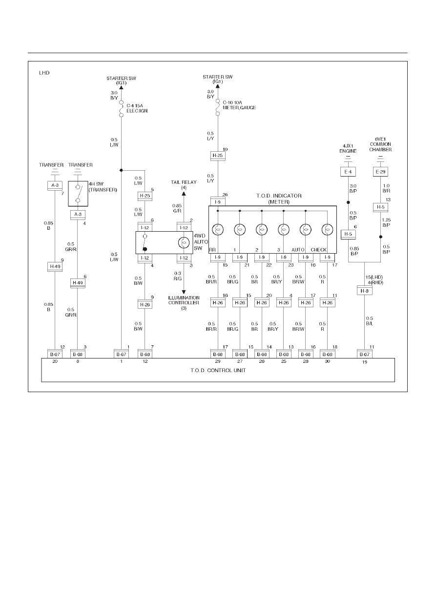
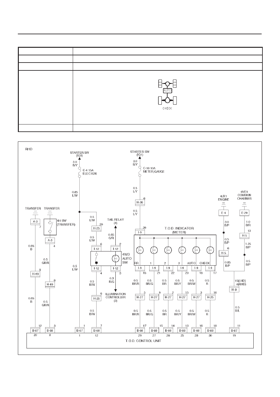
DRIVE LINE CONTROL SYSTEM (TOD)
4B2–84
D04RY00115

4B2–85
DRIVE LINE CONTROL SYSTEM (TOD)
Step
Action
Yes
No
1
1. Turn on the starter switch.
When the transfer lever is shifted to the high position, is 5V
observed between terminals 8 and 19 (4H switch)?
Go to Step 2
Go to Step 4
2
When the transfer lever is shifted to the 4L position, is 5V
observed between terminals 8 and 19 (4H switch)?
Go to Step 3
Go to Step 4
3
When the transfer lever is shifted to the neutral position, is 0V
observed between terminals 8 and 19 (4H switch)?
Replace the
ECU.
Go to Step 13
Go to Step 4
4
1. Turn off the starter switch.
2. Disconnect the ECU connector.
3. Turn on the starter switch.
When the transfer lever is shifted to the high position, is 12V
observed between terminals 8 and 19 (4H switch)?
Go to Step 5
Go to Step 7
5
When the transfer lever is shifted to the neutral position, is 0V
observed between terminals 8 and 19 (4H switch)?
Go to Step 6
Go to Step 7
6
When the transfer lever is shifted to the 4L position, is 12V
observed between terminals 8 and 19 (4H switch)?
The 4H switch
circuit is
short-circuited
between ECU
and transfer on
battery.Repair the
circuit.
Go to Step 13
Go to Step 7
7
Turn off the starter switch.
When the transfer lever is shifted to the neutral position, is the
continuity established between terminals 8 and 19 (4H switch)?
Go to Step 8
Go to Step 10
8
When the transfer lever is shifted to the high position, is the
continuity established between terminals 8 and 19?
Go to Step 11
Go to Step 9
9
When the transfer lever is shifted to the 4L position, is the
continuity established between terminals 8 and 19?
Go to Step 12
The ECU has
failed.
Replace the
ECU.
Go to Step 13
10
When the transfer lever is shifted to the neutral position, is the
continuity established between terminals (A–3)4 and (A–3)7?
The 4H switch
circuit is broken
between ECU
and
transfer.Repair
the circuit.
Go to Step 13
Repair the
transfer
assembly.
Go to Step 13
11
When the transfer lever is shifted to the high position, is the
continuity established between transfer connector terminals
(A–3)4 and (A–3)7?
Repair the
transfer
assembly.
Go to Step 13
Repair the 4HSW
circuit.
Go to Step 13
12
When the transfer lever is shifted to the 4L position, is the
continuity established between transfer connector terminals
(A–3)7 and (A–3)4?
Repair the
transfer
assembly.
Go to Step 13
Repair the 4H
SW circuit.
Go to Step 13

DRIVE LINE CONTROL SYSTEM (TOD)
4B2–86
Step
No
Yes
Action
13
Check that all the parts are mounted.
Is this step complete?
Repeat the
“Diagnosis Flow”.
Return to Step 13
4B2–87
DRIVE LINE CONTROL SYSTEM (TOD)
Chart C–2
The 4H switch circuit is short-circuited to GND.
Function of circuit
—
Fail condition
When the transfer lever is shifted to 4L, the indicator lamp status is not changed.
Indicator lamp status
Transfer position
4L
D04RY00114
Нет комментариевНе стесняйтесь поделиться с нами вашим ценным мнением.
Текст