Opel Frontera UBS. Service manual — part 972
3C – 20 FRONT SUSPENSION
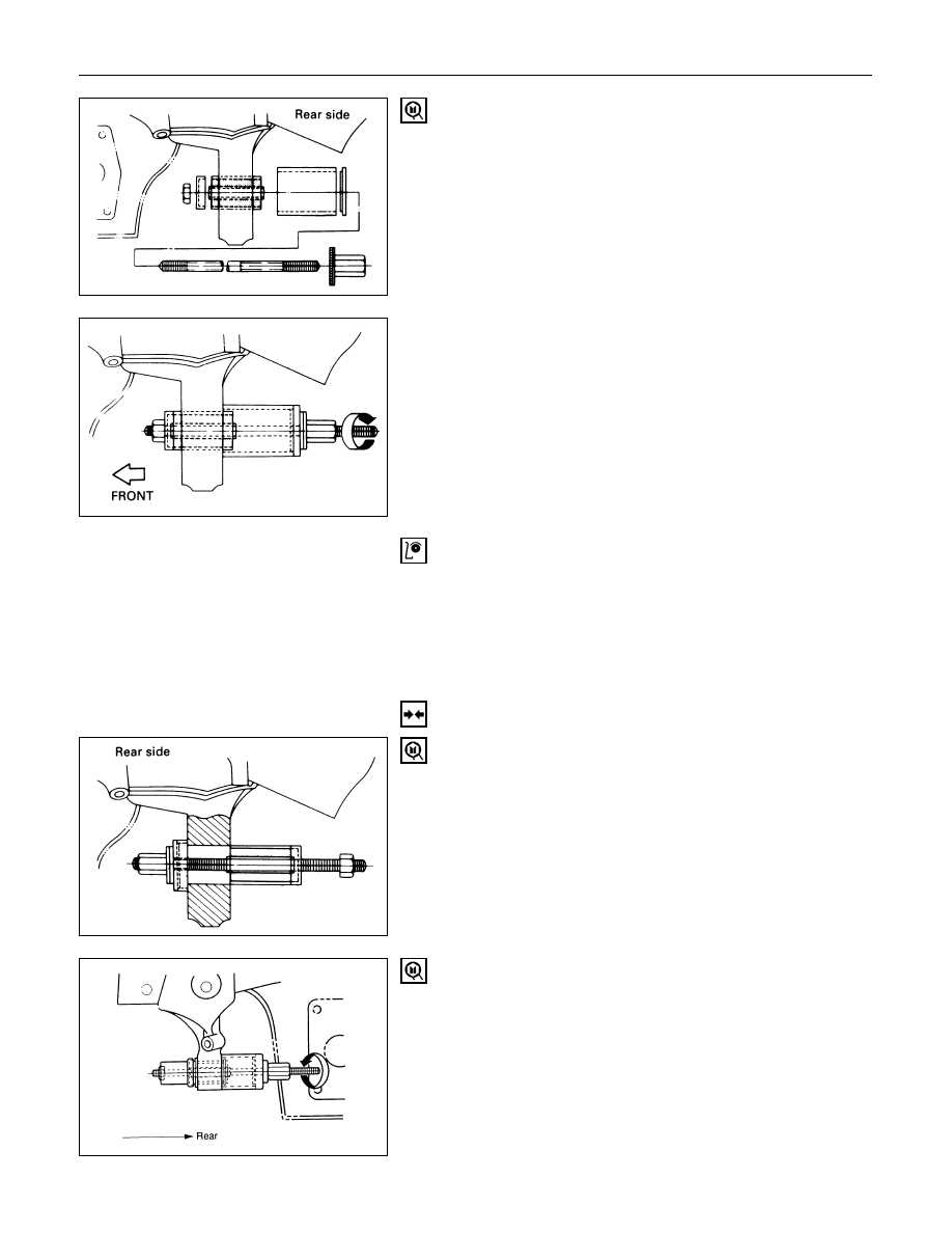
14. Bushing, Rear
Remover: 5-8840-2124-0 (J-36834)
INSPECTION AND REPAIR
Make necessary correction or parts replacement if wear,
damage, corrosion or any other abnormal condition are
found through inspection.
Check the following parts:
•
Lower control arm
•
Bushing
INSTALLATION
14. Bushing, Rear
Installer: 5-8840-2124-0 (J-36834)
13. Bushing, Front
Installer: 5-8840-2123-0 (J-36833)
FRONT SUSPENSION 3C – 21
12. Bolt, Lower Ball Joint
11. Bolt, Torsion Bar Arm
10. Lower Control Arm
9. Bolt, Rear
8. Bolt, Front
7. Lower Ball Joint
Lower Ball Joint Nut Torque
N·m (kg·m/lb·ft)
103 (10.5 / 76)
6. Shock Absorber
Shock Absorber Nut Torque
N·m (kg·m/lb·ft)
82 (8.4 / 61)
5. Stabilizer Link
Link Nut Torque
N·m (kg·m/lb·ft)
50 (5.1 / 37)
4. Torsion Bar Arm Bracket
Torsion Bar Arm Bracket Nut Torque
N·m (kg·m/lb·ft)
116 (11.8 / 85)
3. Torsion Bar
Refer to “Torsion Bar” in this section.
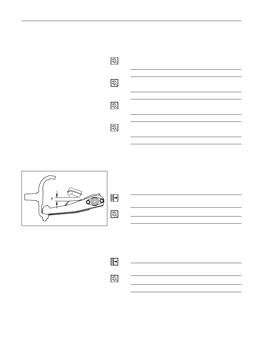
2. Nut and Washer, Rear
Tighten lower link nut finger-tight.
NOTE:
Torque lower control arm nut after adjusting buffer
clearance.
Buffer Clearance (T)
mm (in)
23 (0.91) Wide Tread
24 (0.94) Narrow Tread
Lower Arm Rear Nut Torque
N·m (kg·m/lb·ft)
196 (20.0 / 145)
1. Nut and Washer, Front
Tighten lower link nut finger-tight.
NOTE:
Torque lower control arm nut after adjusting buffer
clearance.
Buffer Clearance (T)
mm (in)
23 (0.91) Wide Tread
24 (0.94) Narrow Tread
Lower Arm Front Nut Torque
N·m (kg·m/lb·ft)
157 (16.0 / 116)
NOTE:
Adjust the trim height. Refer to “Front End Alignment” in
section 2A.
3C – 22 FRONT SUSPENSION
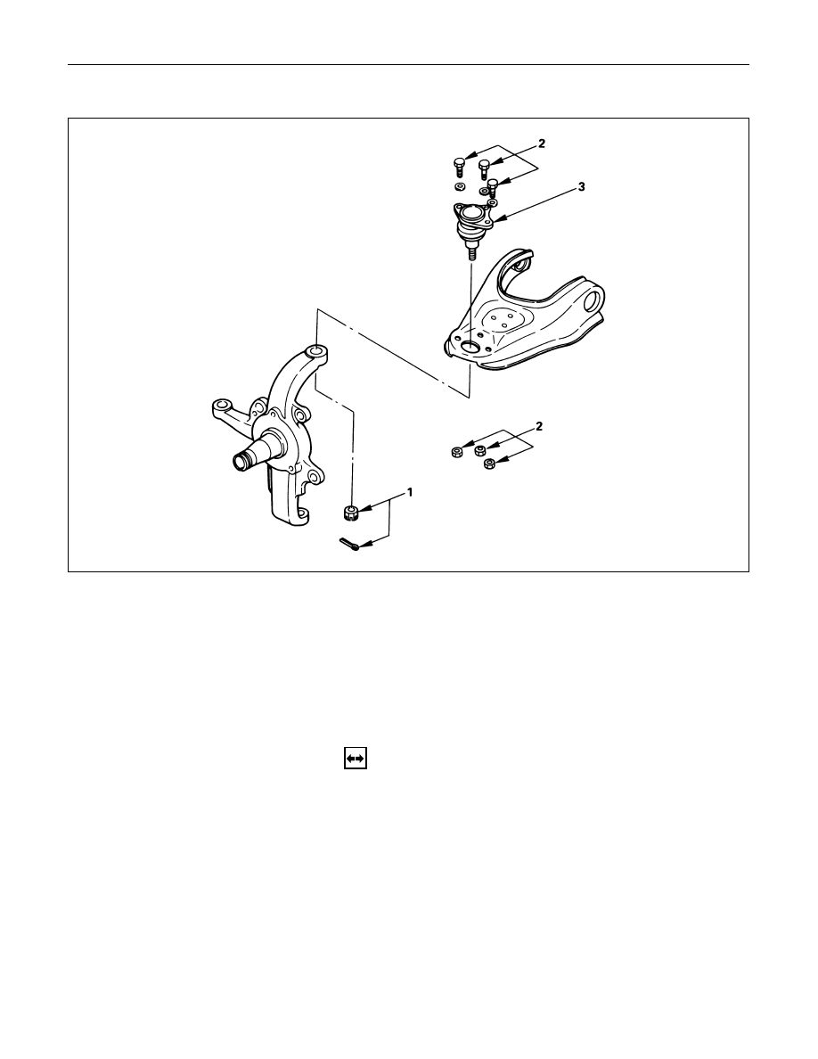
UPPER BALL JOINT
Removal Steps
1.
Nut and cotter pin
2.
Bolt, nut and washer
3.
Upper ball joint
Installation Steps
3.
Upper ball joint
2.
Bolt, nut and washer
1.
Nut and cotter pin
REMOVAL
Preparation:
1)
Raise the vehicle and support the frame with suitable
safety stands.
2)
Remove the speed sensor from the knuckle (If
equipped with ABS).
FRONT SUSPENSION 3C – 23
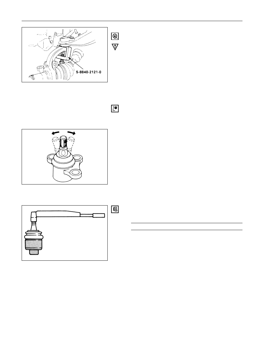
1. Nut and Cotter Pin
Remove the upper ball joint from the knuckle.
Remover: 5-8840-2121-0 (J-36831)
CAUTION:
Be careful not t o break the ball joint boot.
2. Bolt, Nut and Washer
3. Upper Ball Joint
INSPECTION AND REPAIR
Make necessary parts replacement if wear, damage,
corrosion or any other abnormal conditions are found
through inspection.
Inspect the lower end boot for damage or grease leak.
Move the ball joint as shown in the figure to confirm its
normal movement.
Inspect screw/taper area of ball for flaws.
If any defects are found by the above inspections, replace
the ball joint assembly with new one.
After moving the ball joint 4 or 5 times, attach nut then
measure the preload.
Upper Ball Joint Preload
N·m (kg·m/lb·in)
0.5 – 3.2 (0.05 – 0.33 / 4.3 – 28.6)
If the above limits specified are exceeded, replace the
ball joint assembly.
Нет комментариевНе стесняйтесь поделиться с нами вашим ценным мнением.
Текст