Opel Frontera UBS. Service manual — part 911
1B – 38 AIR CONDITIONING
INSTALLATION
To install, follow the removal steps in the reverse order,
noting the following points:
1. If installing a new receiver/drier, be sure to add 30 cc
(0.8 Imp fl oz) of new compressor oil to a new one.
2. Put the receiver/drier in the bracket, and connect with
the refrigerant line. Check that no excessive force is
imposed on the line. Fasten the bracket bolt to the
receiver/drier.
3. Tighten the line to the specified torque.
Refrigerant Line Bolt Torque
N·m (kg·m / lb·in)
6 (0.6 / 52)
4. O-rings cannot be reused. Always replace with new
ones.
5. Be sure to apply new compressor oil to the O-rings
when connecting refrigerant line.
AIR CONDITIONING 1B – 39
Removal Steps
1. Radiator grille
2. Pressure switch connector
3. Pressure switch
Installation Steps
To install, follow the removal steps in the
reverse order.
PRESSURE SWITCH
2
3
1
REMOVAL
Preparation:
•
Disconnect the battery ground cable
•
Discharge and recover refrigerant (Refer to
“REFRIGERANT RECOVERY” in this section.)
1. Radiator Grille
2. Pressure Switch Connector
3. Pressure Switch
When removing the switch connected part, the
connecting part should immediately be plugged or
capped to prevent foreign matter from being mixed
into the line.
INSTALLATION
To install, follow the removal steps in the reverse order,
noting the following points:
1. O-ring cannot be reused. Always replace with a new
one.
2. Be sure to apply new compressor oil to the O-ring
when connecting pressure switch.
3. Tighten the pressure switch to the specified torque.
Pressure Switch Torque
N·m (kg·m / lb·in)
13 (1.3 / 113)
1B – 40 AIR CONDITIONING
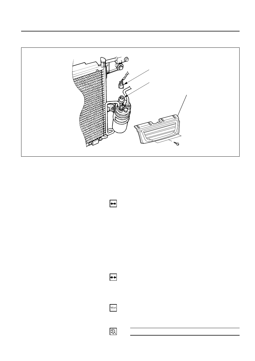
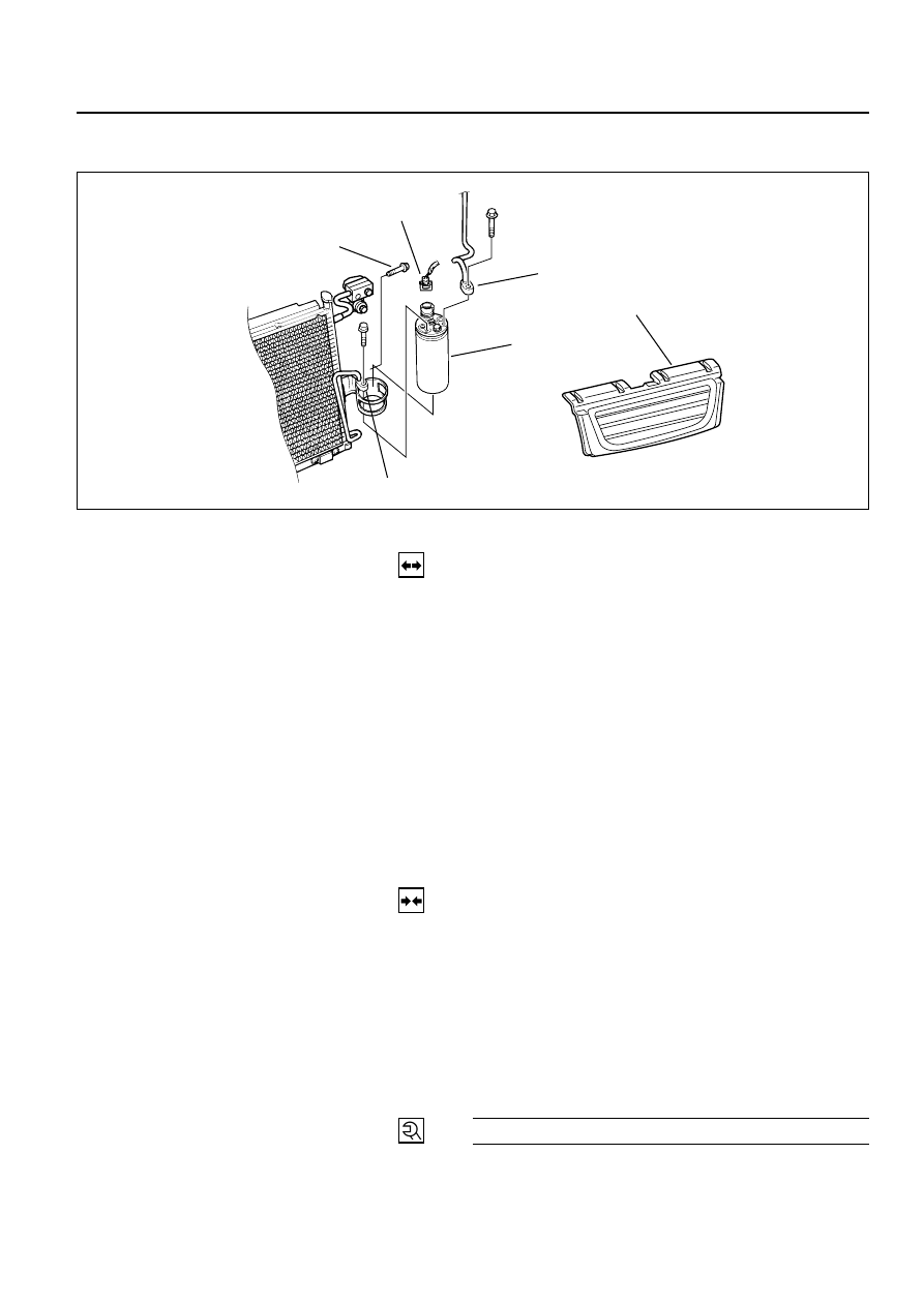
Legend
1. Pressure Switch Connector
2. Refrigerant Line
3. Receiver / Drier
4. Radiator Grille
5. Bracket Bolt
Receiver/Drier and Associated Parts (LHD V6 without Condenser Fan)
4
2
3
2
5
1
REMOVAL
1. Disconnect the battery ground cable
2. Discharge and recover refrigerant
•
Refer to “REFRIGERANT RECOVERY” in this
section.
3. Remove radiator grille.
4. Disconnect pressure switch connector.
5. Disconnect refrigerant line.
•
When removing the line connected part, the
connecting part should immediately be plugged or
capped to prevent foreign matter form being mixed
in to line.
6. Remove bracket bolt.
7. Remove receiver/drier.
•
Loosen the bolt, then, using care not to touch or
bend the refrigerant line, carefully pull out the
receiver/drier.
INSTALLATION
To install, follow the removal steps in the reverse order,
noting the following points:
1. If installing a new receiver/drier, be sure to add
30cc(1.0 fl. oz.) of new compressor oil to a new one.
2. Put the receiver/drier in the bracket and connect with
the refrigerant line. Check that no excessive force is
imposed on the line. Fasten the bracket bolt to the
receiver/drier.
3. Tighten the refrigerant line to the specified torque.
Refrigerant Line Blot Torque
N·m (kg·m / lb·in)
6 (0.6 / 52)
4. O-rings cannot be reused. Always replace with new
ones.
5. Be sure to apply new compressor oil to the O-rings
when connecting the refrigerant line.
875RW002
AIR CONDITIONING 1B – 41
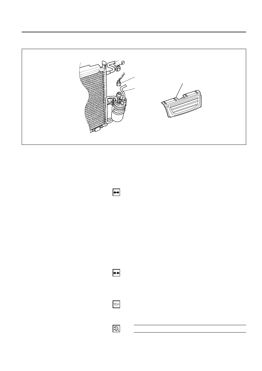
Pressure Switch and Associated Parts
2
3
1
Legend
1. Pressure switch connector
2. Pressure switch
3. Radiator Grille
REMOVAL
Preparation:
•
Disconnect the battery ground cable
•
Discharge and recover refrigerant (Refer to
“REFRIGERANT RECOVERY” in this section.)
1. Radiator Grille
2. Pressure Switch Connector
3. Pressure Switch
When removing the switch connected part, the
connecting part should immediately be plugged or
capped to prevent foreign matter from being mixed
into the line.
INSTALLATION
To install, follow the removal steps in the reverse order,
noting the following points:
1. O-ring cannot be reused. Always replace with a new
one.
2. Be sure to apply new compressor oil to the O-ring
when connecting pressure switch.
3. Tighten the pressure switch to the specified torque.
Pressure Switch Torque
N·m (kg·m / lb·in)
13 (1.3 / 113)
875RW005
Нет комментариевНе стесняйтесь поделиться с нами вашим ценным мнением.
Текст