Opel Frontera UBS. Service manual — part 75
POWER STEERING 2A – 21
REMOVAL
Preparation:
•
Place a drain pan below the pump.
1.
Hose, Suction
2.
Hose, Flexible
3.
Bolt
4.
Pump Assembly
INSTALLATION
4.
Pump Assembly
3.
Bolt
Bolt Torque
N·m (kg·m/lb·ft)
22 (2.2 / 16)
2.
Hose, Flexible
Hose, Bolt Torque
N·m (kg·m/lb·ft)
54 (5.5 / 40)
1.
Hose, Suction
Fill and bleed the system. Refer to “Bleeding the
Power Steering System” in this section.
2A – 22 POWER STEERING
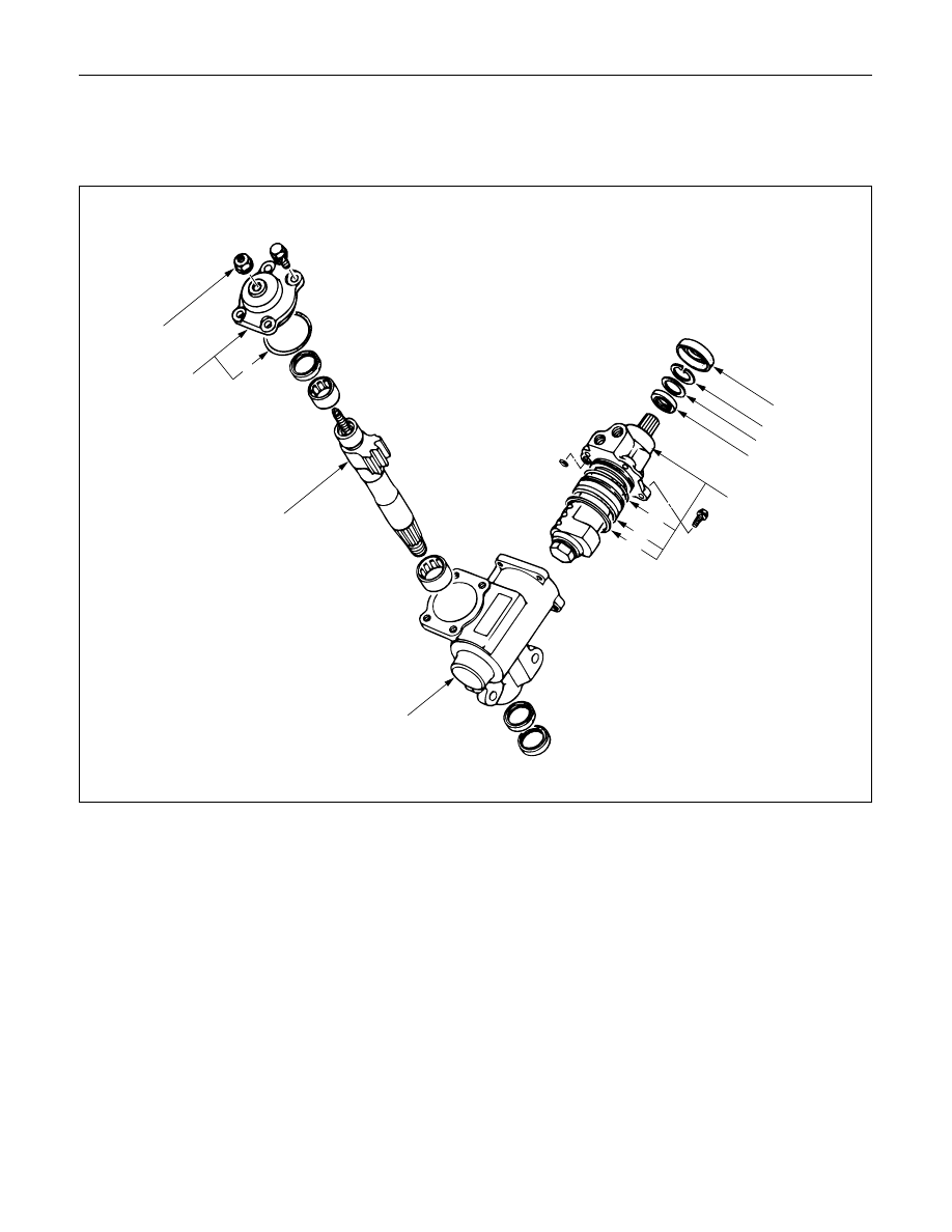
UNIT REPAIR
STEERING GEAR
5
These steps are based on the LHD model
6
8
13
1
2
3
4
9
10
11
12
7
Disassembly Steps
1.
Dust cover
2.
Retaining ring
3.
Back up ring
4.
Oil seal
5.
Lock nut
6.
Top cover assembly
7.
O-ring
8.
Sector shaft
9.
Ball-nut and valve housing assembly
10.
O-ring
11.
Seal ring
12.
O-ring
13.
Gear box
Reassembly Steps
13.
Gear box
12.
O-ring
11.
Seal ring
10.
O-ring
9.
Ball-nut and valve housing assembly
8.
Sector shaft
7.
O-ring
6.
Top cover assembly
5.
Lock nut
4.
Oil seal
3.
Back up ring
2.
Retaining ring
1.
Dust cover
440RW004
These steps are based on the LHD model.
POWER STEERING 2A – 23
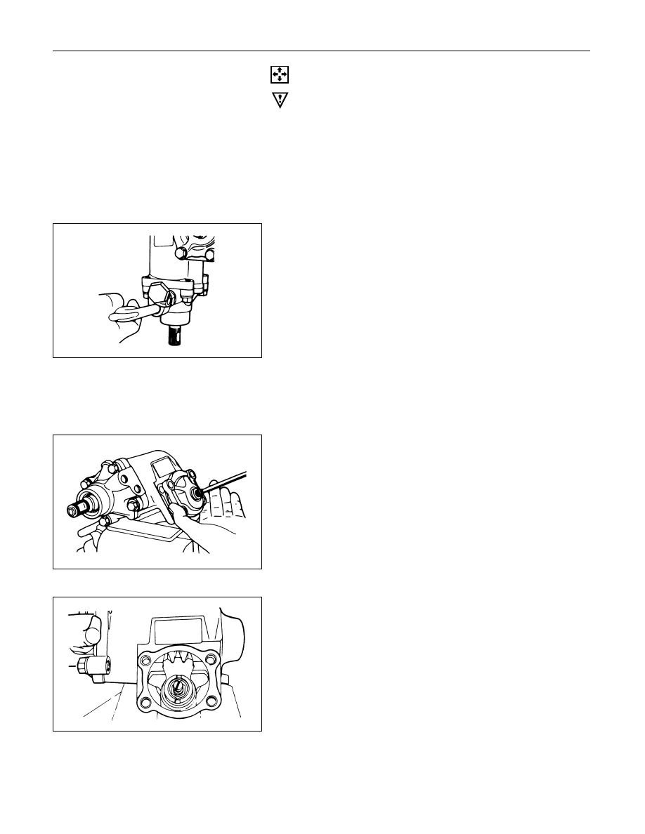
DISASSEMBLY
CAUTION:
Do not clamp the steering gear assembly in a vise by the
power cylinder housing.
1.
Dust Cover
2.
Retaining Ring
3.
Back up RIng
4.
Oil Seal
1) Clean the faces of the extended stub shaft.
2) Plug the hose fitting on the inlet side.
3) Remove the oil seal by blowing compressed air
through the hole in the outlet side.
5.
Lock Nut
Remove the adjusting screw lock nut and turn the
adjusting screw counterclockwise to remove the
preload between the sector gear and the rack piston,
then remove the top cover bolts.
6.
Top Cover Assembly
Holding the top cover stationary, turn the adjusting
screw clockwise to raise and free to cover, then
remove the cover.
7. O-ring
8. Sector Shaft
Bring the stub shaft into straight-ahead position. Do
not force the sector shaft off the gear box with a
hammer or other impact tools.
2A – 24 POWER STEERING
9. Ball-nut and Valve Housing Assembly
It is strongly advisable to always keep the ball nut
and valve housing assembly in a horizontal position,
or the rack piston will fall off onto the end of the
worm, causing the rack piston to slip out of the worm
shaft and the balls to fall out.
10. O-ring
11. Seal Ring
12. O-ring
13. Gear Box
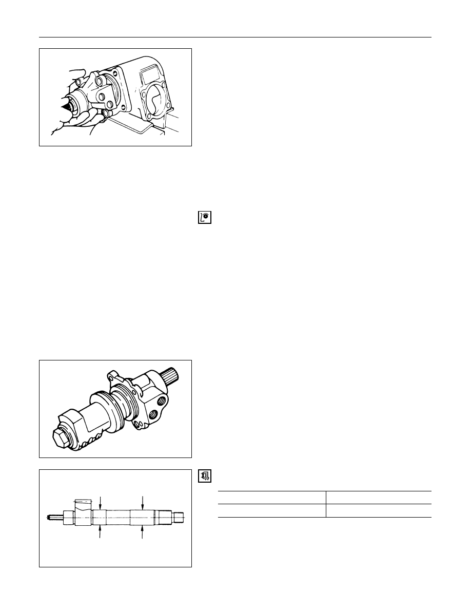
INSPECTION AND REPAIR
Inspect the following parts for wear, damage or any other
abnormal conditions.
•
Bearing
•
Ball-nut and valve housing
•
Sector shaft
•
Top cover
•
Gear box
•
Needle bearing
•
Dust seal
•
Seal ring
•
Gasket
Ball-nut Rotation
Hold the ball nut and valve housing assembly vertically
and see if the ball-nut lower by turning smoothly. If the
ball-nut does not lower smoothly, check the worm shaft
for bending and foreign matter.
NOTE:
When testing the ball nut and valve housing assembly, do
not let it travel all the way to the end of worm shaft, or
damage to the ball tubes will result.
Check sector shaft outside diameter.
Sector Shaft Outside Diameter
mm(in)
Standard
Limit
32.0 (1.260)
31.7 (1.248)
Нет комментариевНе стесняйтесь поделиться с нами вашим ценным мнением.
Текст