Opel Frontera UBS. Service manual — part 1389
6E–150
4JX1–TC ENGINE DRIVEABILITY AND EMISSIONS
Diagnostic Trouble Code (DTC) P1488 (Flash DTC 72)
Intake Throttle Motor Control Circuit Signal Gap
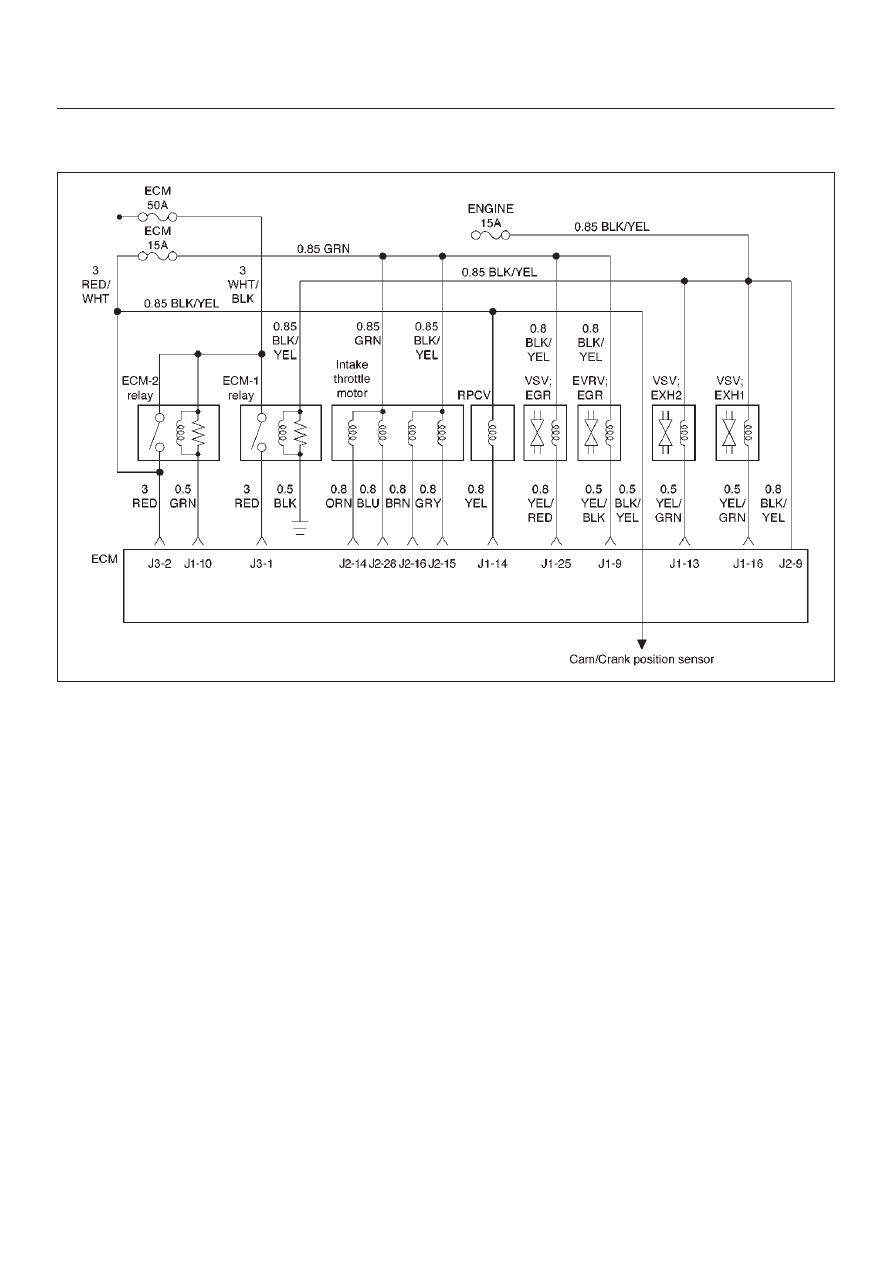
060RW135
Circuit Description
The Intake throttle position (ITP) sensor circuit provides a
voltage signal that changes relative to throttle blade
angle.
Action Taken When the DTC Sets
D
The ECM will store conditions which were present
when the DTC was set as Freeze Frame and in the
Failure Records data.
Conditions for Clearing the MIL/DTC
D
DTC P1488 can be cleared by using the Tech 2 “Clear
Info” function or by disconnecting the ECM battery
feed.
Diagnostic Aids
Check for the following conditions:
D
Poor connection at ECM – Inspect harness connectors
for backed-out terminals, improper mating, broken
locks, improperly formed or damaged terminals, and
poor terminal-to-wire connection.
D
Damaged harness – Inspect the wiring harness for
damage. If the harness appears to be OK, observe the
throttle position display on the Tech 2 while moving
connectors and wiring harnesses related to the ITP
sensor. A change in the display will indicate the
location of the fault.
If DTC P1488 cannot be duplicated, the information
included in the Failure Records data can be useful in
determining vehicle mileage since the DTC was last set.

6E–151
4JX1–TC ENGINE DRIVEABILITY AND EMISSIONS
DTC P1488 – Intake Throttle Motor Control Circuit Signal Gap
Step
Action
Value(s)
Yes
No
1
Was the “On-Board Diagnostic (OBD) System Check”
performed?
—
Go to
Step 2
Go to
OBD
System
Check
2
1. Ignition “ON,” engine “OFF.”
2. With the throttle closed, observe the “ITP Sensor”
display on the Tech 2.
Is the “ITP Sensor” below the specified value?
0.22 V
Go to
Step 4
Go to
Step 3
3
1. Ignition “ON,” engine “OFF.”
2. Review and record Tech 2 Failure Records data.
3. Operate the vehicle within Failure Records
conditions as noted.
4. Using a Tech 2, monitor the “Specific DTC” info for
DTC P1488.
Does the Tech 2 indicate DTC P1488 failed?
—
Go to
Step 4
Refer to
Diagnostic
Aids
4
Check the ITP circuit for a poor connection at the ECM
and replace the terminal if necessary.
Did the terminal require replacement?
—
Verify repair
Go to
Step 5
5
Check the Intake throttle motor circuit for a poor
connection and replace the terminal if necessary.
Did the terminal require replacement?
—
Verify repair
Go to
Step 6
6
Check the ITP Assembly for a poor connection at the
TP sensor and fasten the ITP Assembly if necessary.
Did the ITP Assembly require repair?
—
Verify repair
Go to
Step 7
7
Replace the ECM (Refer to the Data Programming in
Case of ECM change).
Is the action complete?
—
Verify repair
—
6E–152
4JX1–TC ENGINE DRIVEABILITY AND EMISSIONS
Diagnostic Trouble Code (DTC) P0502 (Flash DTC 24)
VSS (Vehicle Speed Sensor) No Signal
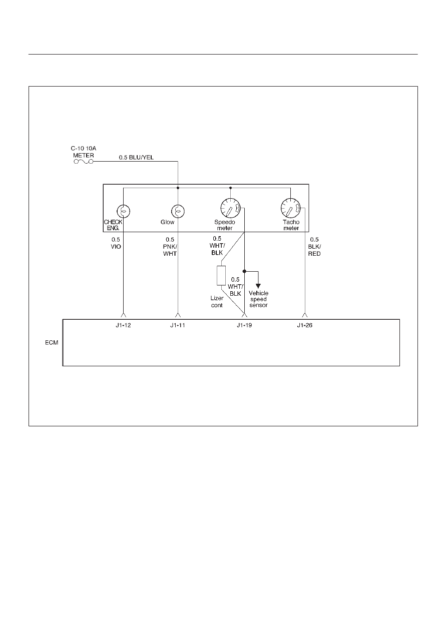
060RW136
Circuit Description
The vehicle speed sensor has a magnet rotated by the
transmission output shaft. Attached to the sensor is a hall
effect circuit the interacts with the magnetic field treated
by the rotating magnet. A 12-volt operating supply for the
speed sensor hall circuit is supplied from the meter fuse.
The VSS pulses to ground the 9-volt signal sent from the
engine control module (ECM) on the reference circuit.
The ECM interprets vehicle speed by the number of
pulses to ground per second on the reference circuit.
Action Taken When the DTC Sets
D
The ECM will illuminate the malfunction indicator lamp
(MIL) the first time the fault is detected.
D
The ECM will store conditions which were present
when the DTC was set as Freeze Frame and in the
Failure Records data.
Conditions for Clearing the MIL/DTC
D
DTC P0502 can be cleared by using the Tech 2 “Clear
Info” function or by disconnecting the ECM battery
feed.

6E–153
4JX1–TC ENGINE DRIVEABILITY AND EMISSIONS
Test Description
Number(s) below refer to the step number(s) on the
Diagnostic Chart.
10. To avoid backprobing the VSS and possibly
damaging a seal or terminal, the VSS output can be
tested at the point where the transmission harness
connected to the engine harness. The green 16-way
connector is adjacent to a blue 16-way connector,
and it can be easily accessed by removing the air
cleaner assembly. The green 16-way connector is
separated, and battery voltage is applied to the VSS
through the yellow wire at one corner of the
connector. The VSS output can be monitored with a
DVM connected to the blue wire with a black tracer.
The two wires are next to each other in the 16-way
connector . The test connections are made on the
transmission side of the connector, the side that is
not clipped to the body sheetmetal.
11. The speedometer-to-ECM VSS signal wire is
spliced to a wire leading to the cruise control
module. If a short to ground or voltage is found
between the ECM and speedometer, it could be
located between the splice and the cruise control
module.
DTC P0502 –VSS No Signal
Step
Action
Value(s)
Yes
No
1
Was the “On-Board Diagnostic (OBD) System Check”
performed?
—
Go to
Step 2
Go to
OBD
System
Check
2
Does the speedometer work?
—
Go to
Step 10
Go to
Step 3
3
1. Disconnect the VSS connector.
2. Ignition “ON.”
3. Using a test light to battery +, probe the connector
ground wire.
Did the light illuminate?
—
Go to
Step 5
Go to
Step 4
4
Repair the sensor ground.
Is the action complete?
—
Verify repair
—
5
1. Ignition “ON,” sensor disconnected.
2. Using a DVM, measure at the VSS connector
between ground and voltage supply.
Was the measurement near the specified value?
Battery
voltage
Go to
Step 7
Go to
Step 6
6
Repair the open or short to ground which may have
blown the meter fuse.
Is the action complete?
—
Verify repair
—
7
1. Ignition “ON,” VSS disconnected.
2. Using a DVM, measure at the VSS connector
between ground and the blue/black wire from the
speedometer.
Was the measurement near the specified value?
7.5-8 V
Go to
Step 9
Go to
Step 8
8
Check for an open or short circuit between the
speedometer and the VSS.
Was an open or short circuit located?
—
Verify repair
Go to
Step 9
9
Replace the VSS.
Is the action complete?
—
Verify repair
Go to
Step 10
10
Replace the speedometer.
Is the action complete?
—
Verify repair
Go to
Step 11
Нет комментариевНе стесняйтесь поделиться с нами вашим ценным мнением.
Текст