Opel Frontera UBS. Service manual — part 1387
6E–142
4JX1–TC ENGINE DRIVEABILITY AND EMISSIONS
Diagnostic Trouble Code (DTC) P1475 (Flash DTC 71)
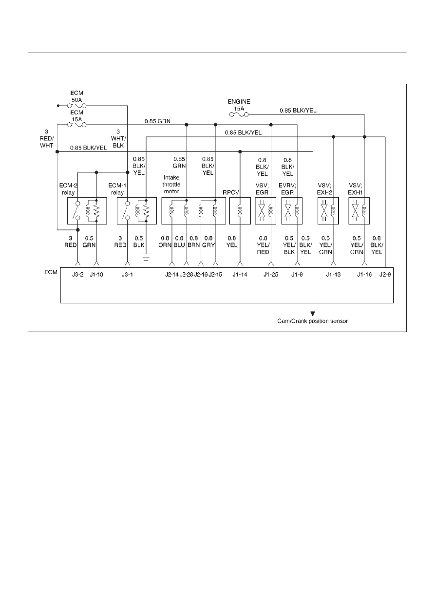
EXH #2 VSV Circuit Open/Short
060RW135
Circuit Description
EXH. #1, #2 VSV Circuit receives current through Engine
15A fuse, #1 and #2 being connected in parallel.
Action Taken When the DTC Sets
D
The ECM will illuminate the malfunction indicator lamp
(MIL) the first time the fault is detected.
D
The ECM will store conditions which were present
when the DTC was set as Freeze Frame and in the
Failure Records data.
Conditions for Clearing the MIL/DTC
D
DTC P1475 can be cleared by using the Tech 2 “Clear
Info” function or by disconnecting the ECM battery
feed.
Diagnostic Aids
Check for the following conditions:
D
Poor connection at ECM – Inspect harness connectors
for backed-out terminals, improper mating, broken
locks, improperly formed or damaged terminals, and
poor terminal-to-wire connection.
D
Damaged harness – Inspect the wiring harness for
damage.

6E–143
4JX1–TC ENGINE DRIVEABILITY AND EMISSIONS
DTC P1475 – EXH #2 VSV Circuit Open/Short
Step
Action
Value(s)
Yes
No
1
Was the “On-Board Diagnostic (OBD) System Check”
performed?
—
Go to
Step 2
Go to
OBD
System
Check
2
1. Ignition “ON,” engine “OFF.” Review and record
Tech 2 Failure Records data.
2. Operate the vehicle within Failure Records
conditions as noted.
3. Using a Tech 2, monitor the “ DTC” info for DTC
P1475.
Does the Tech 2 indicate DTC P1475 failed this
ignition?
—
Go to
Step 3
Refer to
Diagnostic
Aids
3
1. Ignition “OFF.”
2. Disconnect the EXH #2 connectors.
3. Check the EXH #2 circuit for a short to ground.
Is the EXH #2 circuit shorted to ground?
—
Verify repair
Go to
Step 4
4
Replace the EXH #2 VSV.
Is the action complete?
—
Verify repair
Go to
Step 5
5
1. Ignition “ON,” engine “OFF.” Review and record
Tech 2 Failure Records data.
2. Operate the vehicle within Failure Records
conditions as noted.
3. Using a Tech 2, monitor the “ DTC” info for DTC
P1475.
Does the Tech 2 indicate DTC P1475 failed this
ignition?
—
Go to
Step 6
—
6
Replace the ECM (Refer to the Data Programming in
Case of ECM change).
Is the action complete?
—
Verify repair
—
6E–144
4JX1–TC ENGINE DRIVEABILITY AND EMISSIONS
Diagnostic Trouble Code (DTC) P1485 (Flash DTC 74)
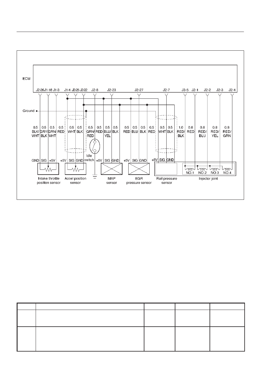
ITP (Intake Thorottle Position) Sensor Low Voltage
060RW134
Circuit Description
The intake throttle position (ITP) sensor circuit provides a
voltage signal that changes relative to throttle blade
angle.
Action Taken When the DTC Sets
D
The ECM will illuminate the malfunction indicator lamp
(MIL) the first time the fault is detected.
D
The ECM will store conditions which were present
when the DTC was set as Freeze Frame and in the
Failure Records data.
Conditions for Clearing the MIL/DTC
D
DTC P1485 can be cleared by using the Tech 2 “Clear
Info” function or by disconnecting the ECM battery
feed.
Diagnostic Aids
Check for the following conditions:
D
Poor connection at ECM – Inspect harness connectors
for backed-out terminals, improper mating, broken
locks, improperly formed or damaged terminals, and
poor terminal-to-wire connection.
D
Damaged harness – Inspect the wiring harness for
damage.
If the harness appears to be OK, observe the
throttle position display on the Tech 2 while
moving connectors and wiring harnesses related
to the ITP sensor. A change in the display will
indicate the location of the fault.
If DTC P1485 cannot be duplicated, the information
included in the Failure Records data can be useful in
determining vehicle mileage since the DTC was last set.
DTC P1485 –ITP Sensor Low Voltage
Step
Action
Value(s)
Yes
No
1
Was the “On-Board Diagnostic (OBD) System Check”
performed?
—
Go to
Step 2
Go to
OBD
System
Check
2
1. Ignition “ON,” engine “OFF.”
2. With the throttle closed by the hand, observe the
“ITP Sensor” display on the Tech 2.
Is the “ITP Sensor” below the specified value?
0.22 V
Go to
Step 4
Go to
Step 3

6E–145
4JX1–TC ENGINE DRIVEABILITY AND EMISSIONS
DTC P1485 –ITP Sensor Low Voltage
(Cont'd)
Step
No
Yes
Value(s)
Action
3
1. Ignition “ON,” engine “OFF.”
2. Review and record Tech 2 Failure Records data.
3. Operate the vehicle within Failure Records
conditions as noted.
4. Using a Tech 2, monitor the “DTC” info for DTC
P1485.
Does the Tech 2 indicate DTC P1485 failed?
—
Go to
Step 4
Refer to
Diagnostic
Aids
4
Check the ITP sensor signal circuit for a poor
connection at the ECM and replace the terminal if
necessary.
Did the terminal require replacement?
—
Verify repair
Go to
Step 5
5
1. Ignition “ON,” engine “OFF.”
2. Review and record Tech 2 Failure Records data.
3. Operate the vehicle within Failure Records
conditions as noted.
4. Using a Tech 2 monitor the “Specific DTC” info for
DTC P1485.
Dose the Tech 2 indicate DTC P1485 failed?
—
Go to
Step 6
Refer to
Diagnostic
Aids
6
Replace the intake throttle.
Is the action complete?
—
Verify repair
Go to
Step 7
7
Replace the ECM (Refer to the Data Programming in
Case of ECM change).
Is the action complete?
—
Verify repair
—
Нет комментариевНе стесняйтесь поделиться с нами вашим ценным мнением.
Текст