Opel Frontera UBS. Service manual — part 1861
AIR CONDITIONING 1B – 45
Removal
1. Disconnect the battery ground cable.
2. Discharge and recover refrigerant.
•
Refer to Refrigerant Recovery in this section.
3. Remove evaporator assembly.
•
Refer to Evaporator Assembly in this section.
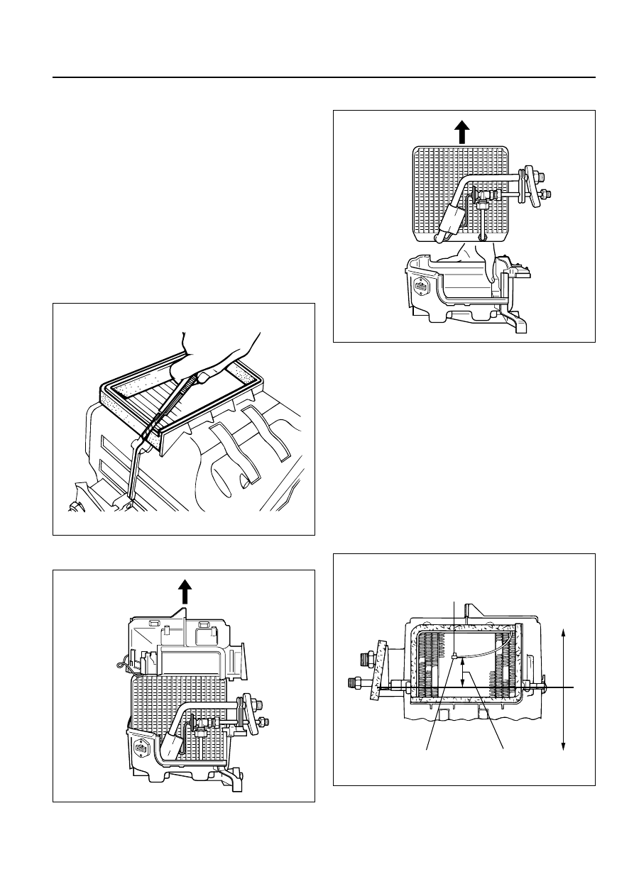
4. Remove pollen filter.
5. Pull the sensor from the evaporator assembly.
6. Remove attaching screw.
7. Remove upper case.
8. Remove lower case.
•
Slit the case parting face with a knife since the
lining is separated when removing the
evaporator.
•
Lift to remove the upper case.
9. Remove evaporator core.
10. Remove expansion valve.
•
Tear off the insulator carefully.
•
Use a back-up wrench when disconnecting all
refrigerant pipes.
Installation
To install, follow the removal steps in the reverse
order, noting the following points:
1. The sensor is installed on the core with the clip.
2. The sensor must not interfere with the
evaporator core.
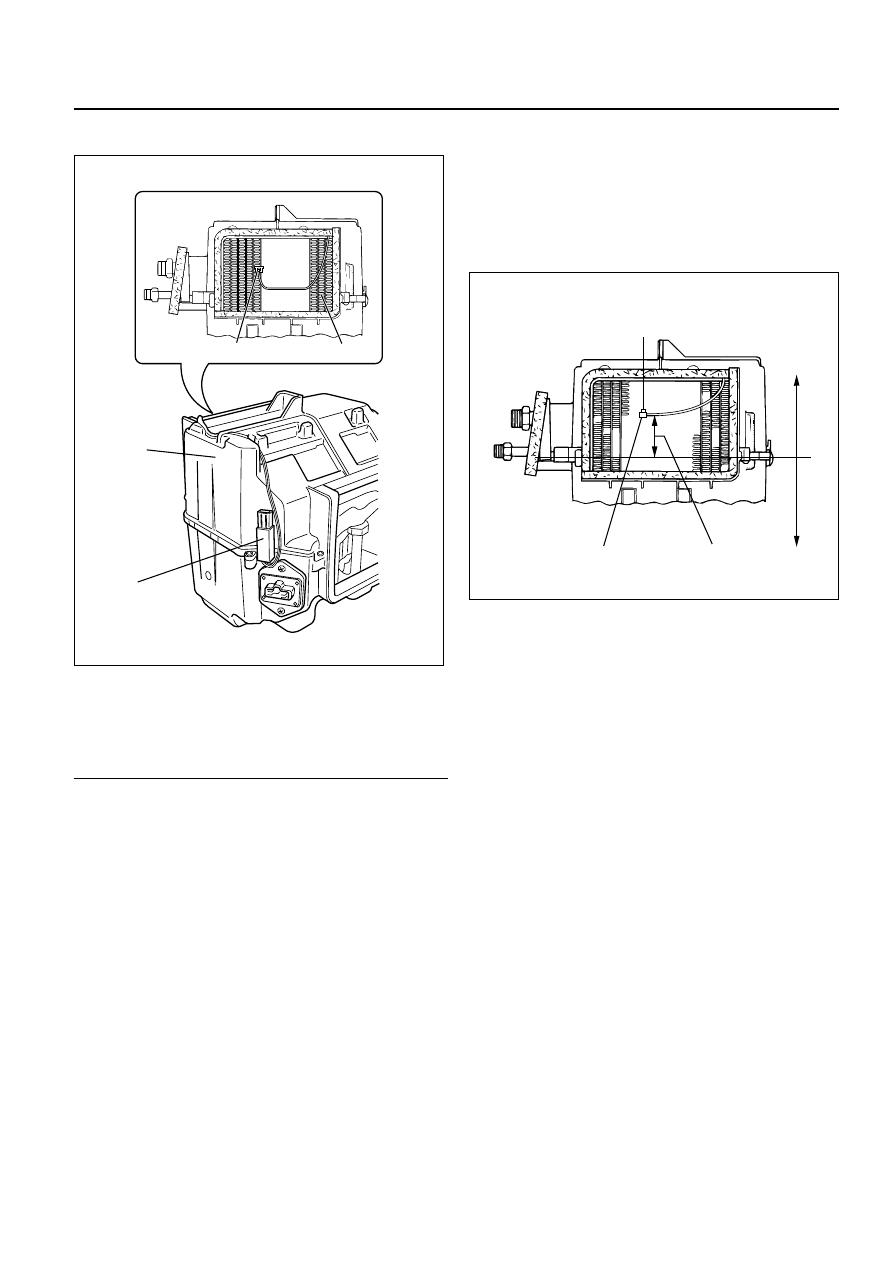
3. When installing the new evaporator core, install
the thermo sensor (2) to the evaporator core (1)
specified position with the clip in the illustration.
874RS006
874RY00005
874RY00006
SENSOR TO BE LOCATED
AT 7TH LINE FROM LEFT
57.5mm(2.26 in.)
2
1
Lower case
Upper case
874RX021
1B – 46 AIR CONDITIONING
4. O-rings cannot be reused, Always replace with
new ones.
5. Be sure to apply new compressor oil to the O-
rings when connecting lines.
6. Be sure to install the sensor and the insulator on
the place where they were before.
7. To install a new evaporator core, add 50cc (1.7
fl. oz.) of new compressor oil to the new core.
8. Tighten the refrigerant lines to the specified
torque. Refer to Main Data and Specifications for
Torque Specifications in this section.
9. Apply an adhesive to the parting face of the
lining when assembling the evaporator
assembly.
AIR CONDITIONING 1B – 47
ELECTRONIC THERMOSTAT
Legend
(1)
Thermo Sensor
(2)
Evaporator Core
(3)
Evaporator
(4)
Thermostat Unit
Removal
1. Disconnect the battery ground cable.
2. Discharge and recover refrigerant.
•
Refer to Refrigerant Recovery in this section.
3. Remove evaporator assembly.
•
Refer to Evaporator Assembly removal
procedure in this section.
4. Remove electronic thermostat.
•
Pull the sensor from the evaporator assembly.
Installation
To install, follow the removal steps in the reverse
order, noting the following points.
1. Install the thermostat sensor to the evaporator
core specified position with the clip.
2. The sensor is installed on the core with the clip
and it must not interfere with the core.
1
2
3
4
874RX022
SENSOR TO BE LOCATED
AT 7TH LINE FROM LEFT
57.5mm(2.26 in.)
2
1
Lower case
Upper case
874RX021
1B – 48 AIR CONDITIONING
1
2
3
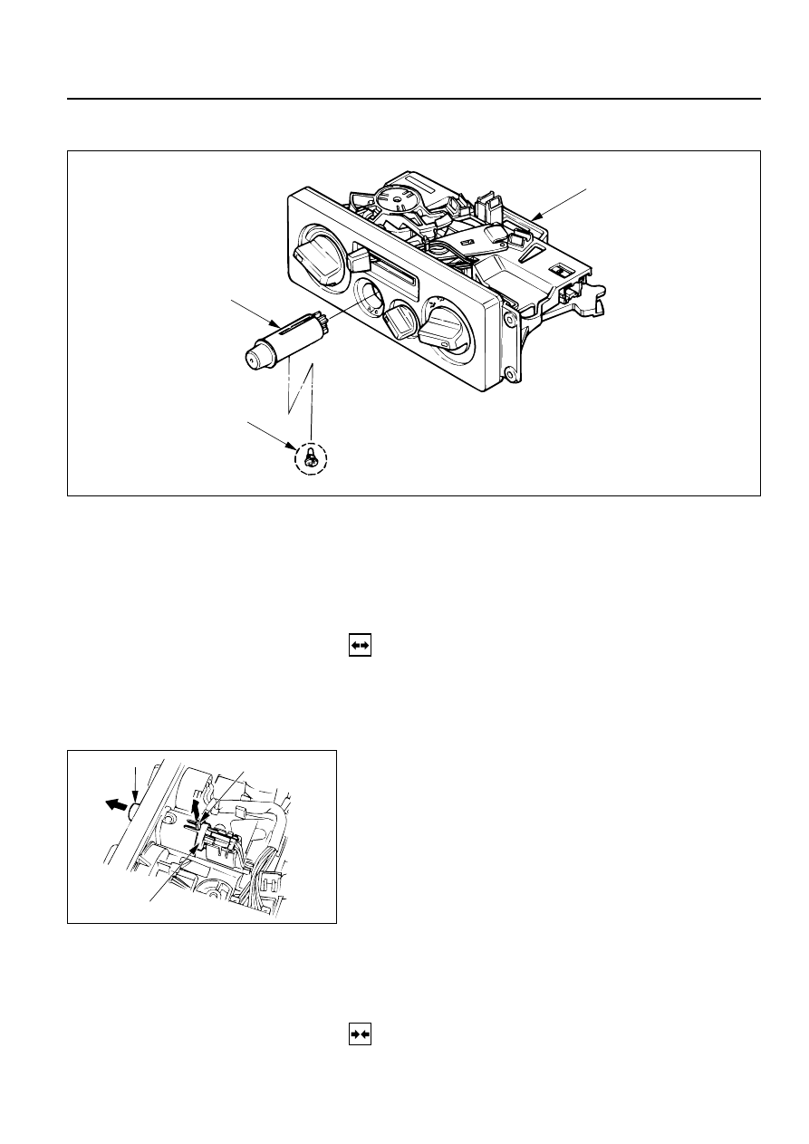
Removal Steps
1. Control lever assembly
2. A/C switch
3. Illumination bulb
Installation Steps
To install, follow the removal steps in the
reverse order.
A/C SWITCH AND ILLUMINATION BULB
REMOVAL
Preparation:
Disconnect the battery ground cable
1. Control Lever Assembly
Refer to Section 1A “CONTROL LEVER ASSEMBLY”
removal procedure.
2. A/C Switch
Raise up the catch portion of the switch and remove
the switch while pushing it toward the outside.
3. Illumination Bulb
Turn the illumination bulb counterclockwise to
remove.
Catch portion
End of switch
A/C switch
INSTALLATION
To install, follow the removal steps in the reverse order.
Нет комментариевНе стесняйтесь поделиться с нами вашим ценным мнением.
Текст