Opel Frontera UBS. Service manual — part 1231

6E–290
ENGINE DRIVEABILITY AND EMISSIONS
Symptoms
Default Section(s)
Initial Diagnosis
Backfire
1. OBD system check.
2. Ignition system.
3. Fuel system diagnosis.
4. Fuel injector and fuel injector
balance test.
5. EGR operation, EGR system
check.
Exhaust System Diagnosis,
Intake Casting Flash, Ignition
System Check
Catalyst Monitor
1. OBD system check.
2. Careful visual/physical inspection.
3. Heated oxygen sensors.
Exhaust System
Fuel Trim
1. OBD system check.
2. Careful visual/physical inspection.
3. Fuel system diagnosis.
4. Heated oxygen sensors, MAF
sensors.
Exhaust System Intake Air
System
Evaporative Emissions
1. OBD system check.
2. Careful visual/physical inspection.
3. Fuel system diagnosis.
—
Heated Oxygen Sensors
1. OBD system check.
2. Careful visual/physical inspection.
Exhaust System
6E–291
ENGINE DRIVEABILITY AND EMISSIONS
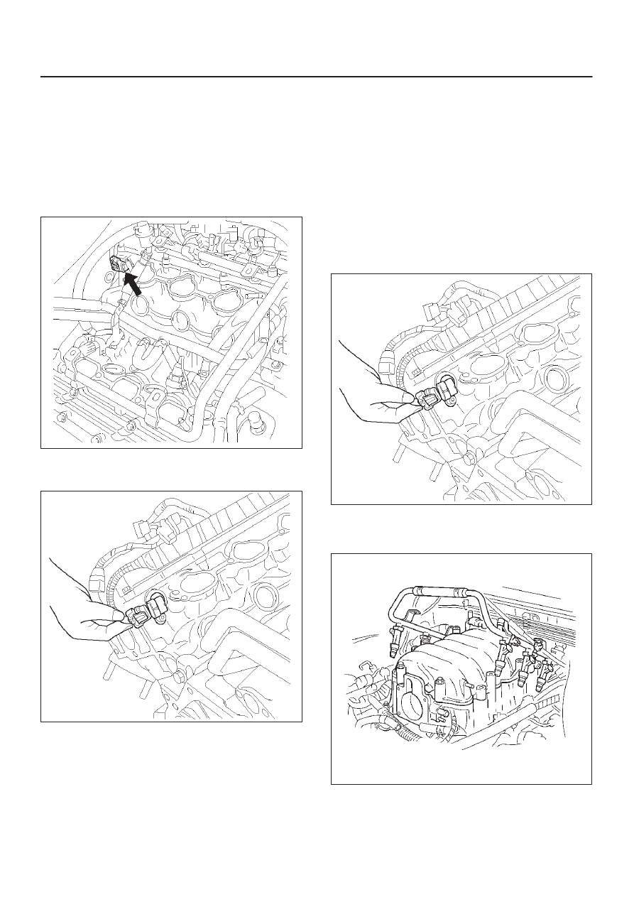
Camshaft Position (CMP)
Sensor
Removal Procedure
1. Disconnect the negative battery cable.
2. Remove the engine cover.
3. Remove the common chamber assembly.
Refer to Common Chamber in Engine Mechanical.
014RW120
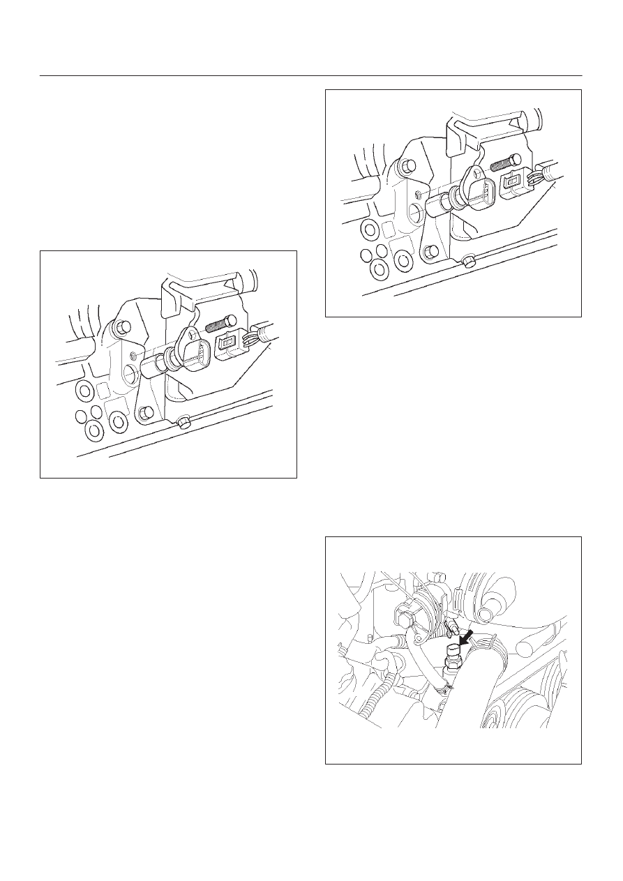
4. Disconnect the electrical connector to the CMP
sensor.
014RV053
5. Remove the CMP retaining bolt from the side of left
cylinder head.
6. Remove the CMP sensor from the cylinder head.
Inspection Procedure
1. Inspect the sensor O-ring for cracks or leaks.
2. Replace the O-ring if it is worn or damaged.
3. Lubricate the new O-ring with engine oil.
4. Install the lubricated O-ring.
Installation Procedure
1. Install the CMP sensor in the cylinder head.
2. Install the CMP sensor retaining bolt.
Tighten
D
Tighten the retaining screw to 9 N·m (78 lb in.).
3. Connect the electrical connector to the CMP sensor.
014RV053
4. Install the common chamber assembly.
Refer to Common Chamber in Engine Mechanical.
014RW106
5. Install the engine cover.
6. Connect the negative battery cable.
6E–292
ENGINE DRIVEABILITY AND EMISSIONS
Crankshaft Position (CKP)
Sensor
Removal Procedure
1. Disconnect the negative battery cable.
2. Disconnect the electrical connector to the CKP
sensor.
3. Remove one bolt and the CKP sensor from the right
side of the engine block, just behind the mount.
NOTE: Use caution to avoid any hot oil that might drip
out.
TS22909
Inspection Procedure
1. Inspect the sensor O-ring for cracks or leaks.
2. Replace the O-ring if it is worn or damaged.
3. Lubricate the new O-ring with engine oil.
4. Install the lubricated O-ring.
Installation Procedure
1. Install the CKP sensor in the engine block.
2. Install the CKP sensor mounting bolt.
Tighten
D
Tighten the mounting bolt to 9 N·m (78 lb in.).
TS22909
3. Connect the electrical connector to the CKP sensor.
4. Connect the negative battery cable.
Engine Coolant Temperature
(ECT) Sensor
Removal Procedure
NOTE: Care must be taken when handling the engine
coolant temperature (ECT) sensor. Damage to the ECT
sensor will affect proper operation of the fuel injection
system.
1. Disconnect the negative battery cable.
2. Drain the radiator coolant. Refer to
Draining and
Refilling Cooling System in Engine Cooling.
3. Disconnect the electrical connector.
014RW127

6E–293
ENGINE DRIVEABILITY AND EMISSIONS
4. Remove the ECT sensor from the coolant crossover.
014RW086
Installation Procedure
1. Apply sealer or the equivalent to the threads of the
ECT sensor.
2. Install the ECT sensor in the coolant crossover.
Tighten
D
Tighten the ECT sensor to 30 N·m (22 lb ft.).
014RW086
3. Connect the electrical connector.
014RW085
4. Fill the radiator with coolant. Refer to
Draining and
Refilling Cooling System in Engine Cooling.
5. Connect the negative battery cable.
Heated Oxygen Sensor (HO2S)
Removal Procedure
1. Disconnect the negative battery cable.
2. Locate the oxygen sensors.
D
Bank 1 sensor 1 is mounted on the right-hand front
exhaust pipe.
TS22912
Нет комментариевНе стесняйтесь поделиться с нами вашим ценным мнением.
Текст