Isuzu Rodeo UE. Service manual — part 532
LIGHTING SYSTEM
8A–15
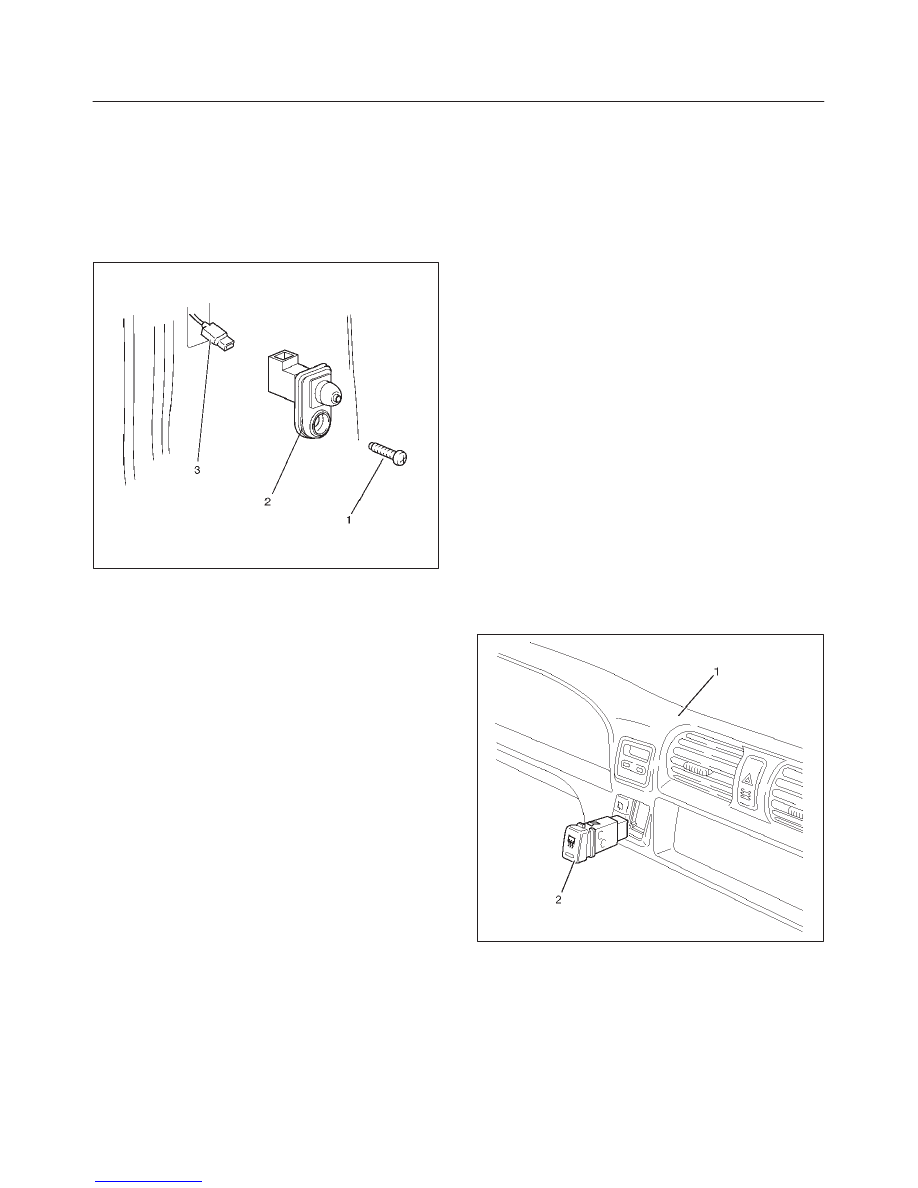
Door Switch
Removal
1. Disconnect the battery ground cable.
2. Remove the door switch (2).
f
Remove the screw (1).
f
Disconnect the connector (3).
825RW289
Installation
To install, follow the removal steps in the reverse order.
Rear Defogger Switch
Removal
1. Disconnect the battery ground cable.
2. Remove the meter cluster assembly (1).
f
Refer to Instrument Panel Assembly in Body
Structure section.
3. Remove the rear defogger switch (2).
f
Disconnect the switch connector.
f
To remove the switch, push the lock from the back
side of the meter cluster assembly.
825RW085
Installation
To install, follow the removal steps in the reverse order.

8A–16
LIGHTING SYSTEM
Key Remind Switch (Starter Switch)
Removal and Installation
Refer to Lock Cylinder in Steering section.
Hazard Warning Light Switch
Removal
1. Disconnect the battery ground cable.
2. Remove the meter cluster assembly (1).
f
Refer to Instrument Panel Assembly in Body
Structure section.
3. Remove the hazard warning switch (2).
f
Disconnect the switch connector.
f
To remove the switch, push the lock from the back
side of the meter cluster assembly.
825RW084
Installation
To install, follow the removal steps in the reverse order.
Stoplight Switch
Removal and Installation
Refer to Stoplight Switch in Brake section.

LIGHTING SYSTEM
8A–17
Backup Light Switch (M/T)
Removal
1. Disconnect the battery ground cable.
2. Remove the backup light switch (1).
f
Disconnect the connector (2).
230RW010
Installation
To install, follow the removal steps in the reverse order,
noting the following point.
1. Apply liquid gasket to the screw portion of the switch
to prevent oil leak.
Turn Signal Light Switch (Combination Switch)
Removal and Installation
Refer to Combination Switch in Steering section.
Illumination Controller
Removal
1. Disconnect the battery ground cable.
2. Remove the instrument panel driver lower cover
assembly (3).
f
Refer to Instrument Panel Assembly in Body
Structure section.
3. Remove the illumination controller (2).
f
Disconnect the controller connector.
f
Remove the controller knob (1).
f
Remove the nut.
f
Remove the controller from the back side of the
instrument panel driver lower cover assembly.
826RW005
Installation
To install, follow the removal steps in the reverse order.
8A–18
LIGHTING SYSTEM
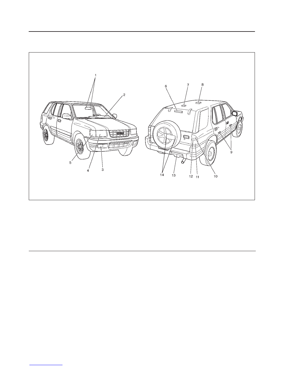
Light and Bulb Specifications
Light and Bulb Specifications
801RX001
Legend
(1) Map Light
(2) Meter
(3) Fog Light
(4) Headlight
(5) Front Turn Signal Light/Front Side Marker
Light/Parking Light
(6) High Mounted Stoplight
(7) Luggage Room Light
(8) Dome Light
(9) Courtesy Light
(10) Rear Turn Signal Light
(11) Taillight/Stoplight
(12) Backup Light
(13) License Plate Light (Bumper Type)
(14) License Plate Light (Tailgate Type)
Нет комментариевНе стесняйтесь поделиться с нами вашим ценным мнением.
Текст