Isuzu Rodeo UE. Service manual — part 176
6E1–75
RODEO X22SE 2.2L ENGINE DRIVEABILITY AND EMISSION
Tech 2
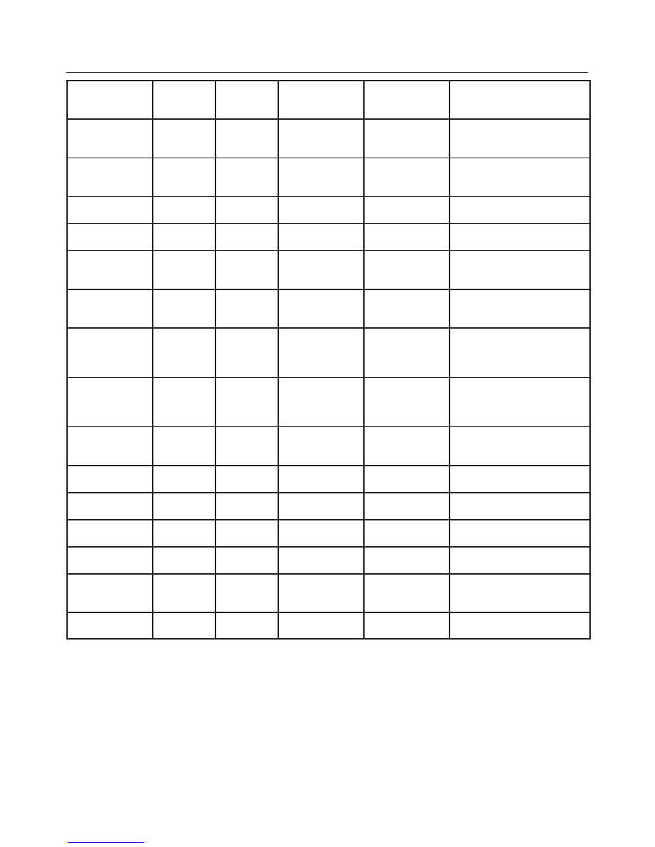
Parameter
Refer To
Typical Data
Values
(2500 RPM)
Typical Data
Values (IDLE)
Units
Displayed
Data List
Weak Cylinder
Engine
Misfire
Cylinder #
–
–
DTC
P0300,P0301,P0302,P0303,
P0304
Misfire Delay
Counter
Engine
Misfire
Counts
0
0
DTC
P0300,P0301,P0302,P0303,
P0304
ABS Rough
Road
Engine
Misfire
Value
Okey
Okey
DTC P1380,P1381
ABS Rough
Road Counts
Engine
Misfire
Counts
0
0
DTC P1380,P1381
B1 O2 Sensor
Ready
Engine
HO2S
Yes/No
Yes
Yes
General Discription and and
Operation, Fuel Control
HO2S. DTC P0135
B1S1 Status
(Bank1,Sensor1
)
Engine
HO2S
Rich/Lean
–
–
General Discription and and
Operation, Fuel Control
HO2S
B1S1 O2
Sensor
(Bank1,Sensor1
)
Engine
HO2S
mV
50 – 950
changing quickly
50 – 950
changing quickly
General Discription and and
Operation, Fuel Control
HO2S
B1S2 O2
Sensor
(Bank1,Sensor2
)
Engine
HO2S
mV
100 – 700
changing slowly
100 – 700
changing slowly
General Discription and and
Operation, Fuel Metering
System
B1S2 O2S
Warm Up Time
Engine
HO2S
sec
0
–
General Discription and and
Operation, Catalyst Monitor
Heated Oxygen Sensor
Fuel Trim
Learned
Engine
HO2S
Yes/No
Yes
Yes
Diagnosis, Fuel Trim Monitor
Fuel Trim Cell
Engine
HO2S
Cell No.
18
2 or 6
Diagnosis, Fuel Trim Cell
Diagnostic Weights
B1 Long Fuel
Trim
Engine
HO2S
%
–
–
DTC P0171,P0172
B2 Short Fuel
Trim
Engine
HO2S
%
–
–
DTC P0171,P0172
Power
Enrichment
Engine
HO2S
Yes/No
No
No
General Discription and and
Operation, Acceleration
Mode
Braodcast Code
–
2.2 letter
–
–
–
6E1–76
RODEO X22SE 2.2L ENGINE DRIVEABILITY AND EMISSION
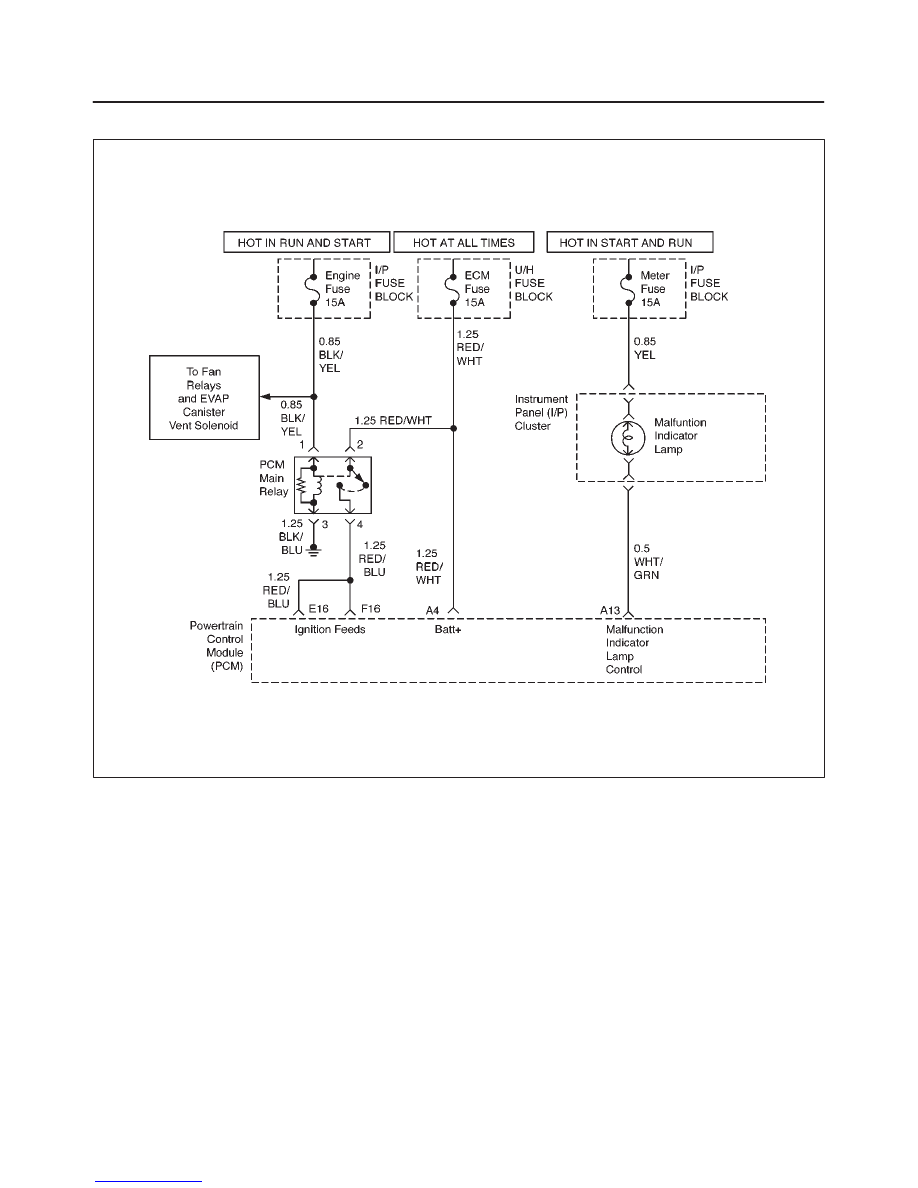
NO MALFUNCTION INDICATOR LAMP (MIL)
D06RX038
Circuit Description
The ”Check Engine” lamp (MIL) should always be
illuminated and steady with the ignition ON and the
engine stopped. Ignition feed voltage is supplied to the
MIL bulb through the meter fuse. The powertrain control
module (PCM) turns the MIL ON by grounding the MIL
driver circuit.
Diagnostic Aids
An intermittent MIL may be caused by a poor connection,
rubbed–through wire insulation, or a wire broken inside
the insulation. Check for the following items:
f
Inspect the PCM harness and connections for
improper mating, broken locks, improperly formed or
damaged terminals, poor terminal–to–wire
connection, and damaged harness.
f
If the engine runs OK, check for a faulty light bulb, an
open in the MIL driver circuit, or an open in the
instrument cluster ignition feed.
f
If the engine cranks but will not run, check for an open
PCM ignition or battery feed, or a poor PCM to engine
ground.
Test Description
Number(s) below refer to the step number(s) on the
Diagnostic Chart:
2. A ”No MIL” condition accompanied by a no–start
condition suggests a faulty PCM ignition feed or
battery feed circuit.
9. Using a test light connected to B+, probe each of
the PCM ground terminals to ensure that a good
ground is present. Refer to PCM Terminal End View
for terminal locations of the PCM ground circuits.
12. In this step, temporarily substitute a known good
relay for the PCM relay. The horn relay is nearby,
and it can be verified as ”good” simply by honking
the horn. Replace the horn relay after completing
this step.
6E1–77
RODEO X22SE 2.2L ENGINE DRIVEABILITY AND EMISSION
17. This vehicle is equipped with a PCM which utilizes
an electrically erasable programmable read only
memory (EEPROM). When the PCM is replaced,
the new PCM must be programmed. Refer to PCM
Replacement and Programming Procedures in
Powertrain Control Module (PCM) and Sensors.
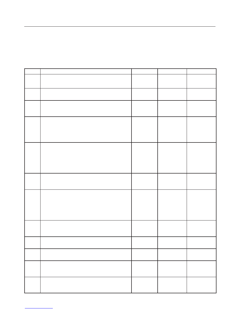
No Malfunction Indicator Lamp (MIL)
Step
Action
Value(s)
Yes
No
1
Was the ”On–Board Diagnostic (OBD) System Check”
performed?
—
Go to Step 2
Go to OBD
System
Check
2
Attempt to start the engine.
Does the engine start?
—
Go to Step 3
Go to Step 6
3
Check the meter fuse for the instrument cluster ignition
feed circuit.
Is the fuse OK?
—
Go to Step 4
Go to Step 16
4
1. Ignition ON.
2. Engine OFF.
3. Probe the ignition feed circuit at the cluster
connector with a test light to ground.
Is the test light ON?
—
Go to Step 5
Go to Step 13
5
1. Ignition OFF.
2. Disconnect the PCM.
3. Jumper the MIL driver circuit at the PCM connector
to ground.
4. Ignition ON.
Is the MIL ON?
—
Go to Step 10
Go to Step 11
6
Check the PCM ignition feed and battery feed fuses
(15A Engine fuse and 15A ECM fuse).
Are both fuses OK?
—
Go to Step 7
Go to Step 15
7
1. Ignition OFF.
2. Disconnect the PCM.
3. Ignition ON.
4. Probe the ignition feed circuit at the PCM harness
connector with a test light to ground.
Is the test light ON?
—
Go to Step 8
Go to Step 12
8
Probe the battery feed circuit at the PCM harness
connector with a test light to ground.
Is the test light ON?
—
Go to Step 9
Go to Step 14
9
Check for a faulty PCM ground connection.
Was a problem found?
—
Verify repair
Go to Step 10
10
Check for damaged terminals at the PCM.
Was a problem found?
—
Verify repair
Go to Step 17
11
Check for an open MIL driver circuit between the PCM
and the MIL.
Was a problem found?
—
Verify repair
Go to Step 18
12
Substitute a known ”good” relay for the PCM main
relay.
Was the malfunction fixed?
—
Verify repair
Go to Step 13
6E1–78
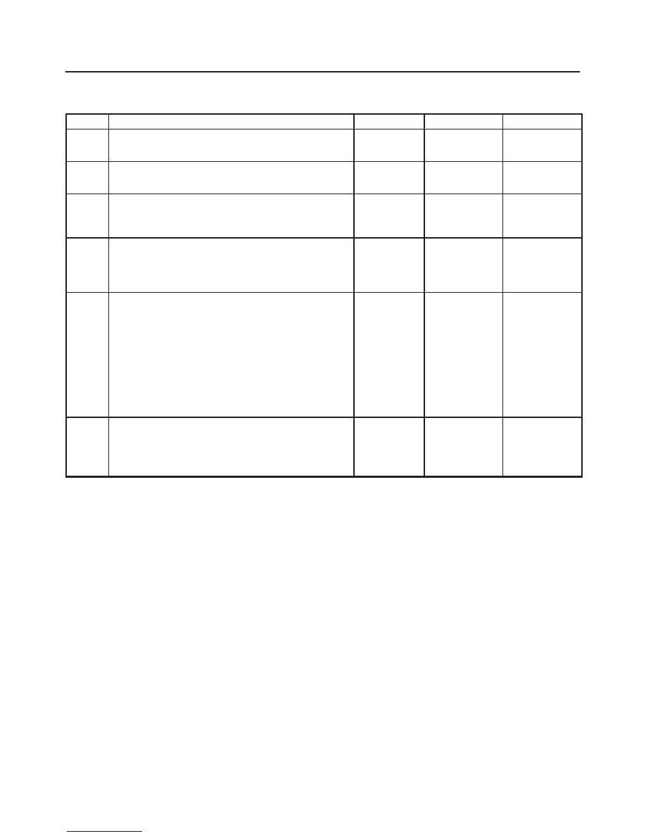
RODEO X22SE 2.2L ENGINE DRIVEABILITY AND EMISSION
No Malfunction Indicator Lamp (MIL)
(Cont'd)
Step
No
Yes
Value(s)
Action
13
Repair the open in the ignition feed circuit.
Is the action complete?
—
Verify repair
—
14
Locate and repair the open PCM battery feed circuit.
Is the action complete?
—
Verify repair
—
15
Locate and repair the short to ground in the PCM
ignition feed circuit or PCM battery feed circuit.
Is the action complete?
—
Verify repair
—
16
Locate and repair the short to ground in the ignition
feed circuit to the instrument cluster, and replace the
fuse.
Is the action complete?
—
Verify repair
—
17
Replace the PCM.
IMPORTANT: The replacement PCM must be
programmed. Refer to PCM in On–Vehicle Service for
procedures.
and also refer to latest service bulletin.
Check to see if the Latest software is released or not.
And then Down Load the LATEST PROGRAMMED
SOFTWARE to the replacement PCM.
—
Verify repair
—
18
Check the MIL driver circuit for a poor connection at the
instrument panel connector.
Was a problem found?
—
Verify repair
Go to
Instrument
Panel in
Electrical
Diagnosis
Нет комментариевНе стесняйтесь поделиться с нами вашим ценным мнением.
Текст