Isuzu Rodeo UE. Service manual — part 17
1A–38 HEATING, VENTILATION AND AIR CONDITIONING (HVAC)
Condition
Correction
Possible cause
Suction (Low Gauge) Pressure
Abnormally Low.
Frost on the expansion valve inlet
line
Expansion valve clogged.
Replace the expansion valve.
Suction (Low Gauge) Pressure
Abnormally Low
Receiver/drier inlet and outlet
refrigerant line temperature. (A
distinct difference in temperature
develops.)
Receiver/Drier clogged.
Replace the receiver/drier.
Suction (Low Gauge) Pressure
Abnormally Low.
Expansion valve outlet refrigerant
line. (Not cold and low pressure
gauge indicates vacuum.)
Expansion valve temperature sensor
is defective.
Replace the expansion valve.
Suction (Low Gauge) Pressure
Abnormally Low.
When the refrigerant line is clogged
or blocked, the low pressure gauge
reading will decrease, or a vacuum
reading may be shown.
Clogged or blocked refrigerant line.
Replace refrigerant line.
Suction (Low Gauge) Pressure
Abnormally Low.
Evaporator core is frozen.
Thermo switch defective.
Replace thermo switch.
Suction (Low Gauge) and Discharge
(High Gauge) Pressure Abnormally
High.
Excessive refrigerant in system.
Discharge and recover the
refrigerant, the Recharge to the
specified amount.
Insufficient cooling.
Condenser clogged or dirty.
Clean the condenser fin.
Suction (Low Gauge) and Discharge
(High Gauge) Pressure Abnormally
High.
Suction (Low) pressure hose (Not
cold).
Air in system.
Evacuate and charge refrigerant.
Suction (Low Gauge) and Discharge
(High Gauge) Pressure Abnormally
Low.
Insufficient cooling
Insufficient refrigerant in system.
Check for leaks. Discharge and
recover refrigerant. Recharge to
specified amount.
A/C — Air Conditioning
HEATING, VENTILATION AND AIR CONDITIONING (HVAC) 1A–39
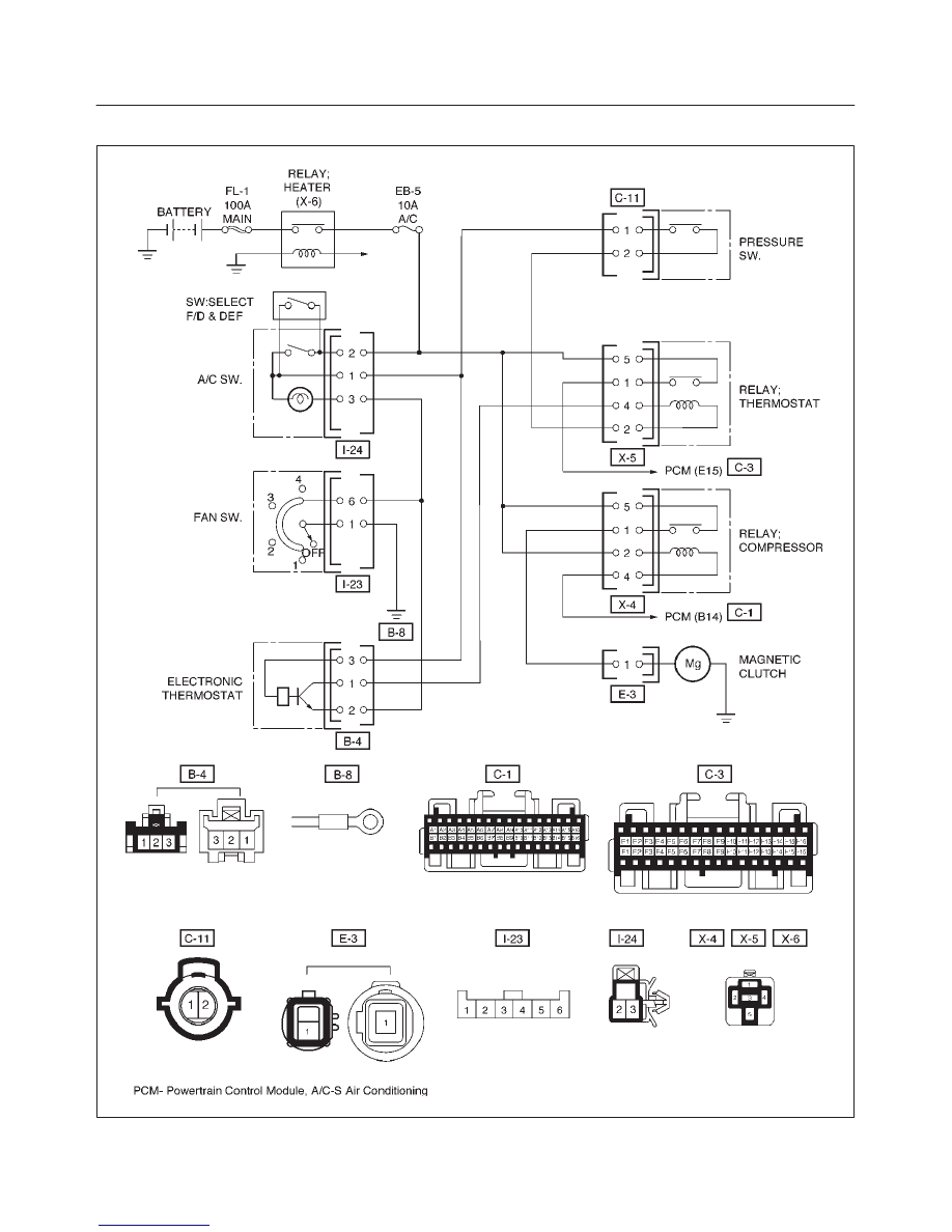
Magnetic Clutch Diagnosis
D08RX002
1A–40 HEATING, VENTILATION AND AIR CONDITIONING (HVAC)
When the air conditioning switch and the fan control knob
(fan switch) are turned on with the engine running, current
flows through the thermostat and the compressor relay to
activate the magnetic clutch.
The air conditioning can be stopped by turning of the air
conditioning switch or the fan control knob (fan switch).
However, even when the air conditioning is in operation,
the electronic thermostat, the pressure switch or the
Powertrain Control Module (PCM;V6-3.2L)/ Engine
Control Module (ECM;L4-2.2L) is used to stop the air
conditioning temporarily by turning off the magnetic clutch
in the prearranged conditions to reduce the engine load
which is being caused by the rise in the engine coolant
temperature, and the acceleration of the vehicle, etc.
For the inspection of the relays, switches and units in the
table, refer to “Individual Inspection” in this section.
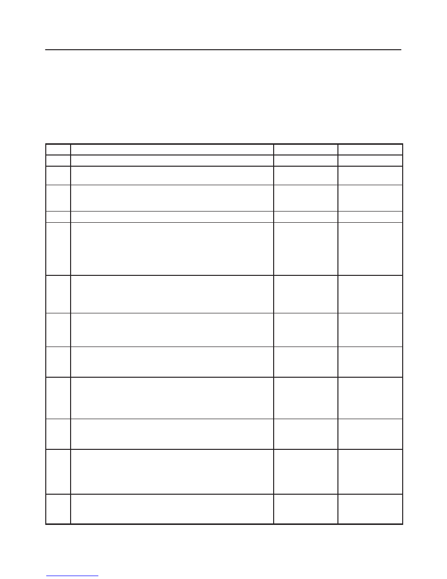
Magnetic Clutch Does Not Run
Step
Action
Yes
No
1
Are No. EB-5 (10A) fuse and No. EB-4 (20A) fuse OK?
Go to Step 2
Replace
2
Are heater (X-6), thermostat (X-5), and compressor (X-4) relays
OK?
Go to Step 3
Replace
3
Is pressure switch OK?
Go to Step 4
Switch defective
or insufficient
refrigerant.
4
Are air conditioning switch and fan control lever (Fan Switch) OK?
Go to Step 5
Replace
5
1. Turn the ignition switch “ON” (Engine is running).
2. Air conditioning switch and fan control lever (Fan Switch)
“ON”.
3. Check to see if battery voltage is present at chassis side
connector terminal No. E3-1.
Is there a battery voltage?
Go to Step 6
Go to Step 7
6
Check to see if continuity between compressor side connector
terminal No. E3-1 and the magnetic clutch side connector
terminal.
Is there a continuity?
Magnetic clutch
defective.
Compressor
defective.
7
Check to see it battery voltage is present at chassis side
connector terminal No.I24-2.
Is there a battery voltage?
Go to Step 8
Open circuit
between No.EB-5
(10A) fuse and
No. I24-2.
8
Check to see if battery voltage is present at chassis side
connector terminal No. C11-1
Is there a battery voltage?
Go to Step 9
Open circuit
between No.I24-1
and No. C11-1.
9
1. Disconnect thermostat relay (X-5).
2. Check to see if battery voltage is present at the chassis side
relay terminal NO. X5-5
Is there a battery voltage?
Go to Step 10
Open circuit
between No.
EB-5 and C11-2
(10A) fuse and
No.X5-5.
10
Check to see if voltage (approx. 10V) is present between chassis
side relay terminal No. X5-2 and No. X5-4.
Is there a battery voltage?
Go to Step 11
Go to Step 17
11
1. Reconnect thermostat relay and disconnect compressor relay
(X-4).
2. Check to see if battery voltage is present at the chassis side
relay terminal No. X4-5.
Is there a battery voltage?
Go to Step 12
Open circuit
between No.
EB-5 (10A) fuse
and No. X4-5.
12
Check to see if continuity between chassis side relay terminal No.
X4-1 and the chassis side connector terminal No. E3-1.
Is there a continuity?
Go to Step 13
Open circuit.
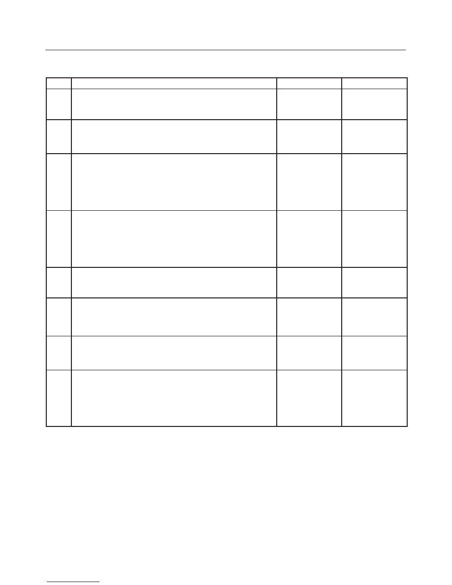
HEATING, VENTILATION AND AIR CONDITIONING (HVAC) 1A–41
Magnetic Clutch Does Not Run (Cont’d)
Step
No
Yes
Action
13
Check to see if battery voltage is present between chassis side
relay terminal No. X4-2 and No. X4-4.
Is there a battery voltage?
Go to Step 14
Go to Step 15
14
Check to see if battery voltage is present at chassis side relay
terminal No. X4-2.
Is there a battery voltage?
Go to Step 16
Open circuit
between No.
EB-5 (10A) fuse
and No. X4-2.
15
Check to see if battery voltage is present at chassis side
connector terminal No. C1-B14.
Is there a battery voltage?
Power train
control module
(PCM) defective.
Refer to
Driveability and
Emissions in
Engine section.
Open circuit
between No.
X4-4 and No.
C1-B14.
16
Check to see if continuity between chassis side relay terminal No.
X5-1 and chassis side connector terminal No. C3-E15.
Is there a continuity?
Power train
control module
(PCM) defective.
Refer to
Driveability and
Emissions in
Engine section.
Open circuit
17
Check to see if battery voltage is present at chassis side relay
terminal No.X5-2.
Is there a battery voltage?
Go to Step 18
Open circuit
between No.X5-2
and C11-2.
18
1. Reconnect thermostat relay.
2. Check to see if battery voltage is present at chassis side
connector terminal No.B4-3.
Is there a battery voltage?
Go to Step 19
Open circuit
between No.I24-1
and No.B4-3.
19
Check to see if battery voltage (appox 10V) is present at chassis
side connector terminal No. B4-1.
Is there a battery voltage?
Go to Step 20
Open circuit
between No.
X5-4 and No.
B4-1.
20
Check to see if continuity between chassis side connector
terminal No. B4-2 and No.I23-6.
Is there a continuity?
Electronic
thermostat
defective.
Open circuit
between No.
B4-2 and
No.I23-6 or poor
ground (Fan
Switch Ground
Circuit).
Нет комментариевНе стесняйтесь поделиться с нами вашим ценным мнением.
Текст