Isuzu Rodeo UE. Service manual — part 18
1A–42 HEATING, VENTILATION AND AIR CONDITIONING (HVAC)
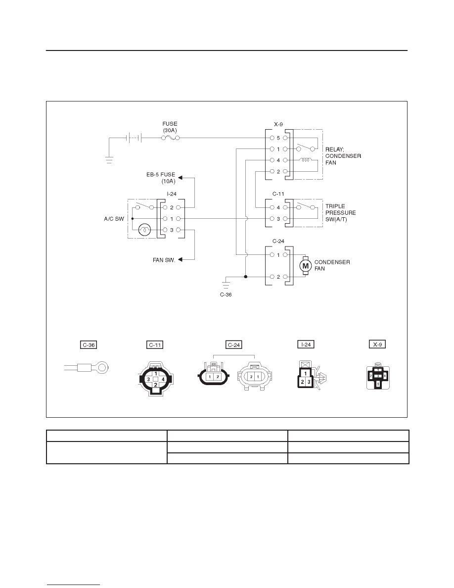
Condenser Fan Diagnosis
While the air conditioning is ON, the cycling switch in the
triple pressure switch senses the refrigerant pressure,
and activates the condenser fan to improve the cooling
capacity of the condenser when the refrigerant pressure
exceeds a set pressure value. The condenser fan stops
when the air conditioning is turned “OFF” or when the
pressure goes down below the set pressure value.
D08RW062
Condition
Possible cause
Correction
Condenser fan does not run.
–
Refer to “Chart A”.
–
Refer to “Chart B”.
HEATING, VENTILATION AND AIR CONDITIONING (HVAC) 1A–43
Chart “A” Condenser Fan Does Not Run
Step
Action
Yes
No
1
Are 30A fuse OK?
Go to Step 2
Replace
2
Is relay (X-9) OK?
Go to Step 3
Replace
3
Is pressure switch OK?
Go to Step 4
Switch defective
or insufficient
refrigerant.
4
Is air conditioning switch OK?
Go to Step 5
Replace
5
Is fan motor OK?
Go to Step 6
Replace
6
1. Disconnect condenser fan relay (X-9).
2. Check to see if battery voltage is present at the chassis side
relay terminal NO. X9-5
Is there a battery voltage?
Go to Step 7
Open circuit
between EB-17
fuse (30A) and
No.X9-5.
7
1. Reconnect condenser fan relay (X-9).
2. Air conditioning switch “ON”.
3. Check to see if battery voltage is present at chassis side
connector terminal No.C11-3.
Is there a battery voltage?
Go to Step 8
Open circuit
between I-24-1
and C11-3.
8
1. Air conditioning switch “OFF”.
2. Check to see if continuity between chassis side relay terminal
No.X9-2 and the chassis side connector terminal No.C11-4.
Is there a continuity?
Go to Step 9
Open circuit.
9
Check to see if continuity between chassis side connector
terminal No. C24-1 and chassis side relay terminal No.X9-1.
Is there a continuity?
Poor ground or
open circuit
between chassis
side connector
terminal No.X9-4
(or No.C24-2)
and body ground
(No.C36).
Open circuit.
Chart “B” Condenser Fan Does Not Stop
Step
Action
Yes
No
1
1. Air conditioning switch “OFF”.
Does condenser fan stop?
Triple pressure
switch defective.
Condenser fan
relay (X9)
defective.
1A–44 HEATING, VENTILATION AND AIR CONDITIONING (HVAC)
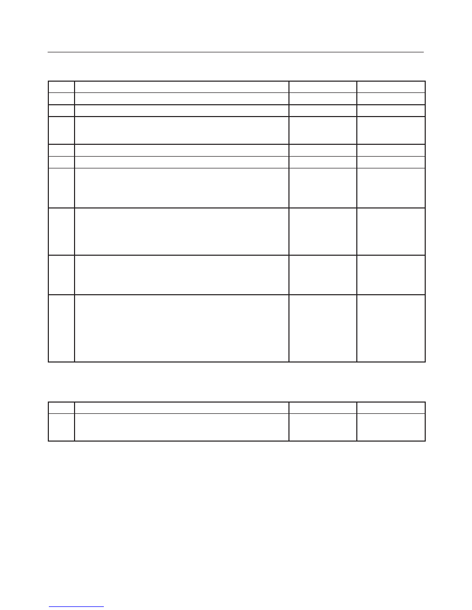
Individual Inspection
Fan Control Knob (Fan Switch) And Air
Conditioning (A/C) Switch
1. Check for continuity between the fan switch and the
A/C switch side connector terminals.
D08RW061
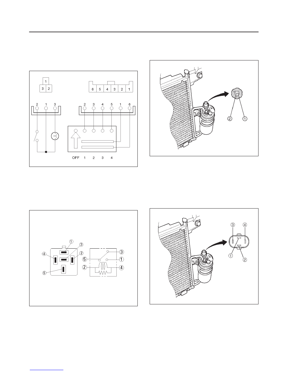
Heater (X-6), Thermostat (X-5), Condenser
Fan (X-9) And Compressor (X-4) Relay
1. Disconnect relays and check for continuity and
resistance between relay terminals.
f
For handling of these relays, refer to Heater Relay
in this section.
825RS179
Pressure Switch
1. Disconnect pressure switch connector and check for
continuity between pressure switch side connector
terminals (1) and (2).
875RW003
Triple Pressure Switch (V6, A/T)
1. Disconnect the connector and check for continuity
between pressure switch side connector terminals (1)
and (2).
2. Reconnect the connector to activate the A/C switch,
and check to see if there is continuity between the
chassis side connector terminals (3) and (4) and the
fan operates.
875RW013
HEATING, VENTILATION AND AIR CONDITIONING (HVAC) 1A–45
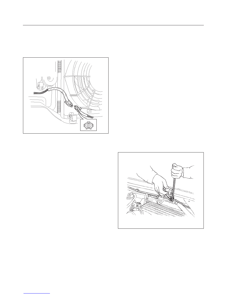
Condenser Fan
1. Disconnect the condenser fan connector.
2. Connect the battery positive terminal to the
condenser fan side connector terminal No.C-24-1
and negative to the No.C-24-2.
3. Check that condenser fan is rotating correctly.
875RW010
General Repair Procedure
Precautions For Replacement or Repair of
Air Conditioning Parts
There are certain procedures, practices and precautions
that should be followed when servicing air conditioning
systems:
f
Keep your work area clean.
f
Always wear safety goggle and protective gloves
when working on refrigerant systems.
f
Beware of the danger of carbon monoxide fumes
caused by running the engine.
f
Beware of discharged refrigerant in enclosed or
improperly ventilated garages.
f
Always disconnect the negative battery cable and
discharge and recover the refrigerant whenever
repairing the air conditioning system.
f
When discharging and recovering the refrigerant, do
not allow refrigerant to discharge too fast; it will draw
compressor oil out of the system.
f
Keep moisture and contaminants out of the system.
When disconnecting or removing any lines or parts,
use plugs or caps to close the fittings immediately.
Never remove the caps or plugs until the lines or parts
are reconnected or installed.
f
When disconnecting or reconnecting the lines, use
two wrenches to support the line fitting, to prevent
from twisting or other damage.
f
Always install new O-rings whenever a connection is
disassembled.
f
Before connecting any hoses or lines, apply new
specified compressor oil to the O-rings.
f
When removing and replacing any parts which
require discharging the refrigerant circuit, the
operations described in this section must be
performed in the following sequence:
1. Use the J-39500 (ACR
4
: HFC-134a Refrigerant
Recovery / Recycling / Recharging / System) or
equivalent to thoroughly discharge and recover the
refrigerant.
2. Remove and replace the defective part.
3. After evacuation, charge the air conditioning
system and check for leaks.
Repair Of Refrigerant Leaks
Refrigerant Line Connections
Install new O-rings, if required. When disconnecting or
connecting lines, use two wrenches to prevent the
connecting portion from twisting or becoming damaged.
852RS003
Нет комментариевНе стесняйтесь поделиться с нами вашим ценным мнением.
Текст