Isuzu Rodeo UE. Service manual — part 404
6E2–371
RODEO 6VD1 3.2L ENGINE DRIVEABILITY AND EMISSIONS
Diagnostic Trouble Code (DTC) P1115 ECT Sensor Circuit Intermittent High
Voltage
D06RW058
Circuit Description
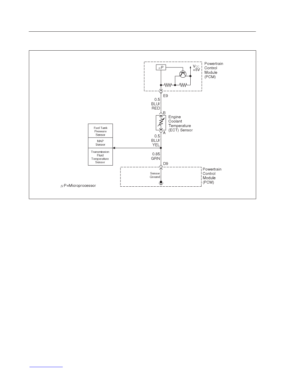
The engine coolant temperature (ECT) sensor is a
thermistor mounted in the engine coolant stream. The
powertrain control module (PCM) applies a voltage
(about 5.0 volts) through a pull-up resistor to the ECT
signal circuit. When the engine coolant is cold, the sensor
(thermistor) resistance is high, therefore the PCM will
measure a high signal voltage. As the engine coolant
warms, the sensor resistance becomes less, and the
ECT signal voltage measured at the PCM drops. With a
fully warmed up engine, the ECT signal voltage should
measure about 1.5 to 2.0 volts. If the PCM detects an
ECT signal that is intermittently above the range of the
ECT sensor, DTC P1115 will set.
Conditions for Setting the DTC
f
Engine running time longer than 90 seconds.
f
The ECT sensor signal is intermittently greater than
–39
°
C (–38
°
F) (about 5 volts) for a total of 10 seconds
over a 100-second period.
Action Taken When the DTC Sets
f
The PCM will not illuminate the malfunction indicator
lamp (MIL).
f
The PCM will store conditions which were present
when the DTC was set as Failure Records data only.
This information will not be stored as Freeze Frame
data.
Conditions for Clearing the MIL/DTC
f
A history DTC P1115 will clear after 40 consecutive
warm-up cycles have occurred without a fault.
f
DTC P1115 can be cleared by using the Tech 2 “Clear
Info” function or by disconnecting the PCM battery
feed.
Diagnostic Aids
Check for the following conditions:
f
Poor connection at PCM – Inspect harness connectors
for backed-out terminals, improper mating, broken
locks, improperly formed or damaged terminals, and
poor terminal-to-wire connection.
f
Damaged harness – Inspect the wiring harness for
damage. If the harness appears to be OK, observe the
ECT display on the Tech 2 while moving connectors
and wiring harnesses related to the ECT sensor. A
change in the ECT display will indicate the location of
the fault.
Reviewing the Failure Records vehicle mileage since the
diagnostic test last failed may help determine how often
the condition that caused the DTC to be set occurs. This
may assist in diagnosing the condition.

6E2–372
RODEO 6VD1 3.2L ENGINE DRIVEABILITY AND EMISSIONS
Engine Coolant Temperature Sensor
°
C
°
F
OHMS
Temperature vs. Resistance Values (approximate)
100
212
177
80
176
332
60
140
667
45
113
1188
35
95
1802
25
77
2796
15
59
4450
5
41
7280
–5
23
12300
–15
5
21450
–30
–22
52700
–40
–40
100700

6E2–373
RODEO 6VD1 3.2L ENGINE DRIVEABILITY AND EMISSIONS
DTC P1115 –ECT Sensor Circuit Intermittent High Voltage
Step
Action
Value(s)
Yes
No
1
Was the “On-Board Diagnostic (OBD) System Check”
performed?
—
Go to
Step 2
Go to
OBD
System
Check
2
Is DTC P0118 also set?
—
Go to
DTC
P0118 chart
first
Go to
Step 3
3
Is DTC P1106, P1111, and/or P1121 also set?
—
Go to
Step 8
Go to
Step 4
4
1. Check for a poor sensor ground circuit terminal
connection at the ECT sensor.
2. If a problem is found, repair as necessary.
Was a problem found?
—
Verify repair
Go to
Step 5
5
1. Check for a poor ECT signal circuit terminal
connection at the ECT sensor.
2. If a problem is found, repair as necessary.
Was a problem found?
—
Verify repair
Go to
Step 6
6
1. Check the ECT signal circuit between the ECT
sensor connector and the PCM for an intermittent
open.
2. If a problem is found, repair as necessary.
Was a problem found?
—
Verify repair
Go to
Step 7
7
1. Check the ECT signal circuit between the ECT
sensor connector and the PCM for an intermittent
short to voltage.
2. If a problem is found, repair as necessary.
Was a problem found?
—
Verify repair
Go to
Step 8
8
1. Check for a poor sensor ground circuit terminal
connection at the PCM.
2. If a problem is found, repair as necessary.
Was a problem found?
—
Verify repair
Go to
Step 9
9
1. Check for an intermittent open or a faulty splice in
the sensor ground circuit.
2. If a problem is found, repair as necessary.
Was a problem found?
—
Verify repair
Refer to
Diagnostic
Aids
6E2–374
RODEO 6VD1 3.2L ENGINE DRIVEABILITY AND EMISSIONS
Diagnostic Trouble Code (DTC) P1121 TP Sensor Circuit Intermittent High
Voltage
D06RW059
Circuit Description
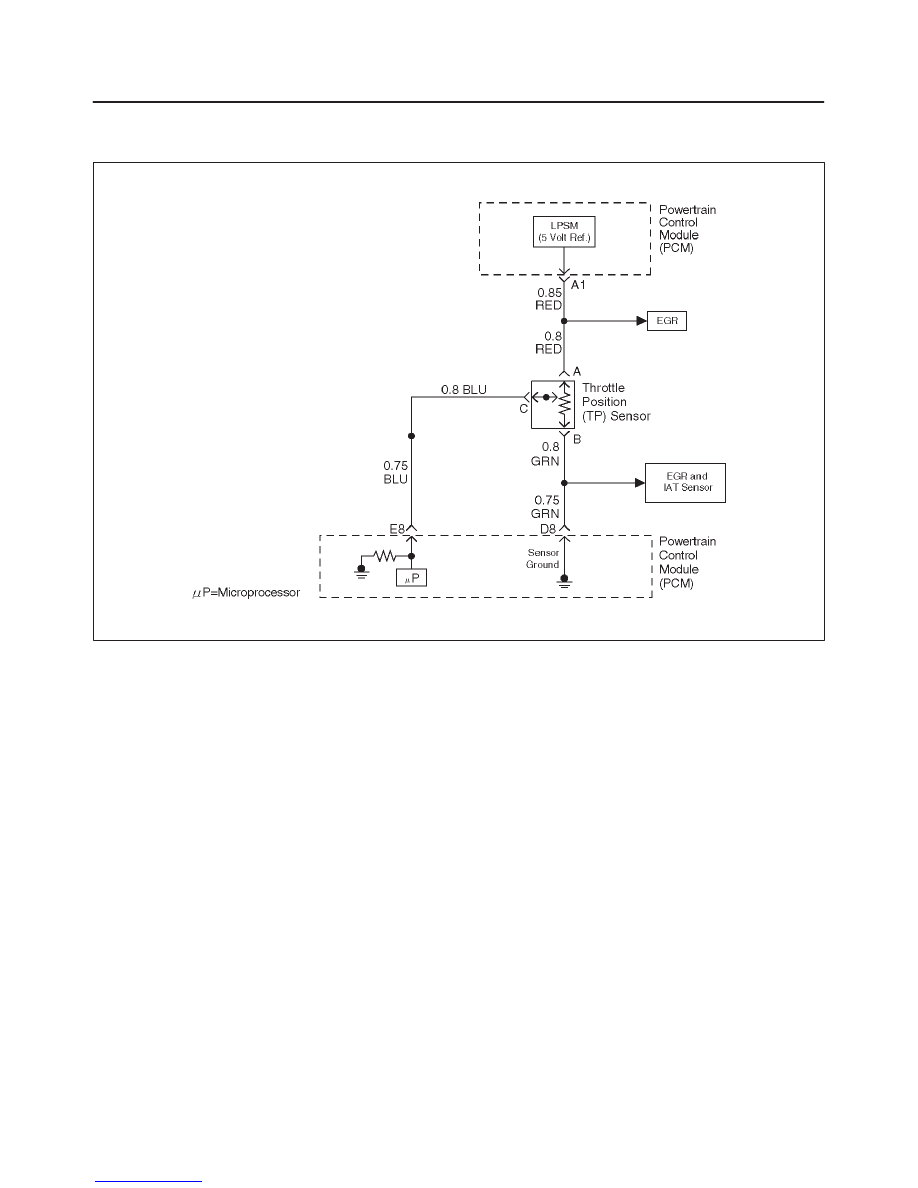
The throttle position (TP) sensor circuit provides voltage
signal that changes relative to the throttle blade angle.
The signal voltage will vary from about 0.6 volts at closed
throttle to about 4.5 volts at wide open throttle (WOT).
The TP signal is one of the most important inputs used by
the powertrain control module (PCM) for fuel control and
for most of the PCM controlled outputs. If the PCM
detects a TP signal that is intermittently above the range
of the TP sensor, DTC P1121 will be set.
Conditions for Setting the DTC
f
The ignition is “ON.”
f
TP sensor indicates a throttle position voltage
intermittently greater than 4.9 volts for a total of 0.15
seconds over a 1.5-second period.
Action Taken When the DTC Sets
f
The PCM will not illuminate the malfunction indicator
lamp (MIL).
f
The PCM will store conditions which were present
when the DTC was set as Failure Records data only.
This information will not be stored as Freeze Frame
data.
Conditions for Clearing the MIL/DTC
f
A history DTC P1121 will clear after 40 consecutive
warm-up cycles have occurred without a fault.
f
DTC P1121 can be cleared by using the Tech 2 “Clear
Info” function or by disconnecting the PCM battery
feed.
Diagnostic Aids
Check for the following conditions:
f
Poor connection at PCM – Inspect the harness
connectors for backed-out terminals, improper mating,
broken locks, improperly formed or damaged
terminals, and poor terminal-to-wire connection.
f
The TP Sensor shares a 5 Volt reference with the EGR
Valve.
If these codes are also set, it could indicate a
problem with the 5 Volt reference circuit or
components itself.
f
The TP Sensor share a ground with the EGR Valve and
the IAT Sensor.
Check the ground if these other DTCs are also
set.
f
Damaged harness – Inspect the wiring harness for
damage. If the harness appears to be OK, observe the
throttle position display on the Tech 2 while moving
connectors and wiring harnesses related to the TP
sensor. A change in the display will indicate the
location of the fault.
If DTC P1121 cannot be duplicated, reviewing the Failure
Records vehicle mileage since the diagnostic test last
failed may help to determine how often the condition that
Нет комментариевНе стесняйтесь поделиться с нами вашим ценным мнением.
Текст